Spring loaded spacer

a technology of spacers and springs, which is applied in the direction of screws, threaded fasteners, shock absorbers, etc., can solve the problems of affecting the life of the appliance in which they are used, affecting the service life of the appliance, so as to achieve the effect of adequate versatility and easy modification

Inactive Publication Date: 2011-12-27
RICHCO
View PDF11 Cites 11 Cited by
  • Summary
  • Abstract
  • Description
  • Claims
  • Application Information

AI Technical Summary

Benefits of technology

[0007]The device which embodies the present invention consists of a barrel portion having at one end means for connecting it to a chassis or the like and at the other end a shank portion having means for connecting it to a printed circuit board or the like. The shank portion is spring loaded with a coiled compression spring seated within the barrel portion. Arranged on the shank end intended for connection to a printed circuit board or the like are a series of circumferential rings, which may be used to fix one or more printed circuit boards or other components to the spacer. This arrangement permits the barrel portion to have a seat consisting of a snap-in engagement with a chassis or a screw or bolt or other mounting. Likewise the shank end connectable to a printed circuit board or the like may be varied to provide various conventional connections to the printed circuit board or like panel.
[0007]The device which embodies the present invention consists of a barrel portion having at one end means for connecting it to a chassis or the like and at the other end a shank portion having means for connecting it to a printed circuit board or the like. The shank portion is spring loaded with a coiled compression spring seated within the barrel portion. Arranged on the shank end intended for connection to a printed circuit board or the like are a series of circumferential rings, which may be used to fix one or more printed circuit boards or other components to the spacer. This arrangement permits the barrel portion to have a seat consisting of a snap-in engagement with a chassis or a screw or bolt or other mounting. Likewise the shank end connectable to a printed circuit board or the like may be varied to provide various conventional connections to the printed circuit board or like panel.
[0010]Another object is to provide a spring loaded spacer which can accommodate one or more printed circuit boards or other components.
[0011]Another object is to provide a spring loaded spacer which can provide continuous and predetermine pressure to a surface on which it is mounted.
[0012]Another object is to provide a spring loaded spacer which can provide continuous and predetermine pressure to a control panel or a photo light sensor secured to a surface on which the spring loaded spacer is mounted.
[0013]Another object is to provide a spring loaded spacer which can be easily modified and is adequately versatile to fix it to a printed circuit board or panel or other components.
[0014]Another object is to provide a spring loaded spacer which replaces several conventional components and which can be used and installed as a single piece.
[0015]Another object is to provide a spring loaded spacer which can be easily modified and adequately versatile to connect it to a chassis or the like by means of a convention snap in, screw, bolt or other conventional fastening means.
[0016]It is also the object of the invention to provide a spring loaded spacer which is inexpensive and simple to fabricate and which is easy, effective and efficient to use.

Problems solved by technology

These assemblies take a significant amount of time and effort to put together.
The parts and printed circuit board are critical and assembly error can result in damage to the equipment or lessen the life of the appliance in which they are used.
Further such parts are not usually interchangeable, and while many fastening systems may be required for a single appliance, separate sub-assemblies are usually required to accomplish the necessary connections.

Method used


Image

  • Spring loaded spacer
  • Spring loaded spacer
  • Spring loaded spacer

Examples


Embodiment Construction

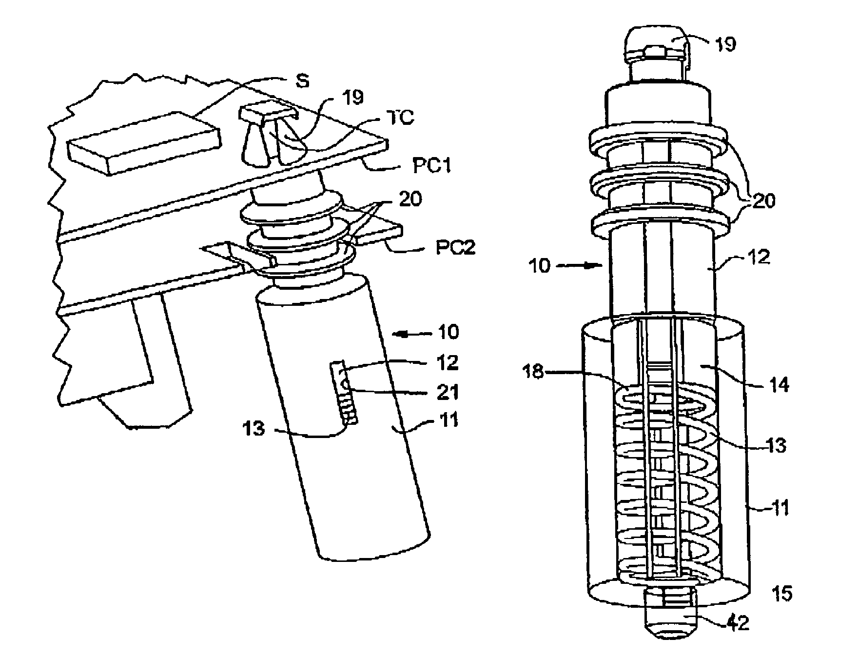
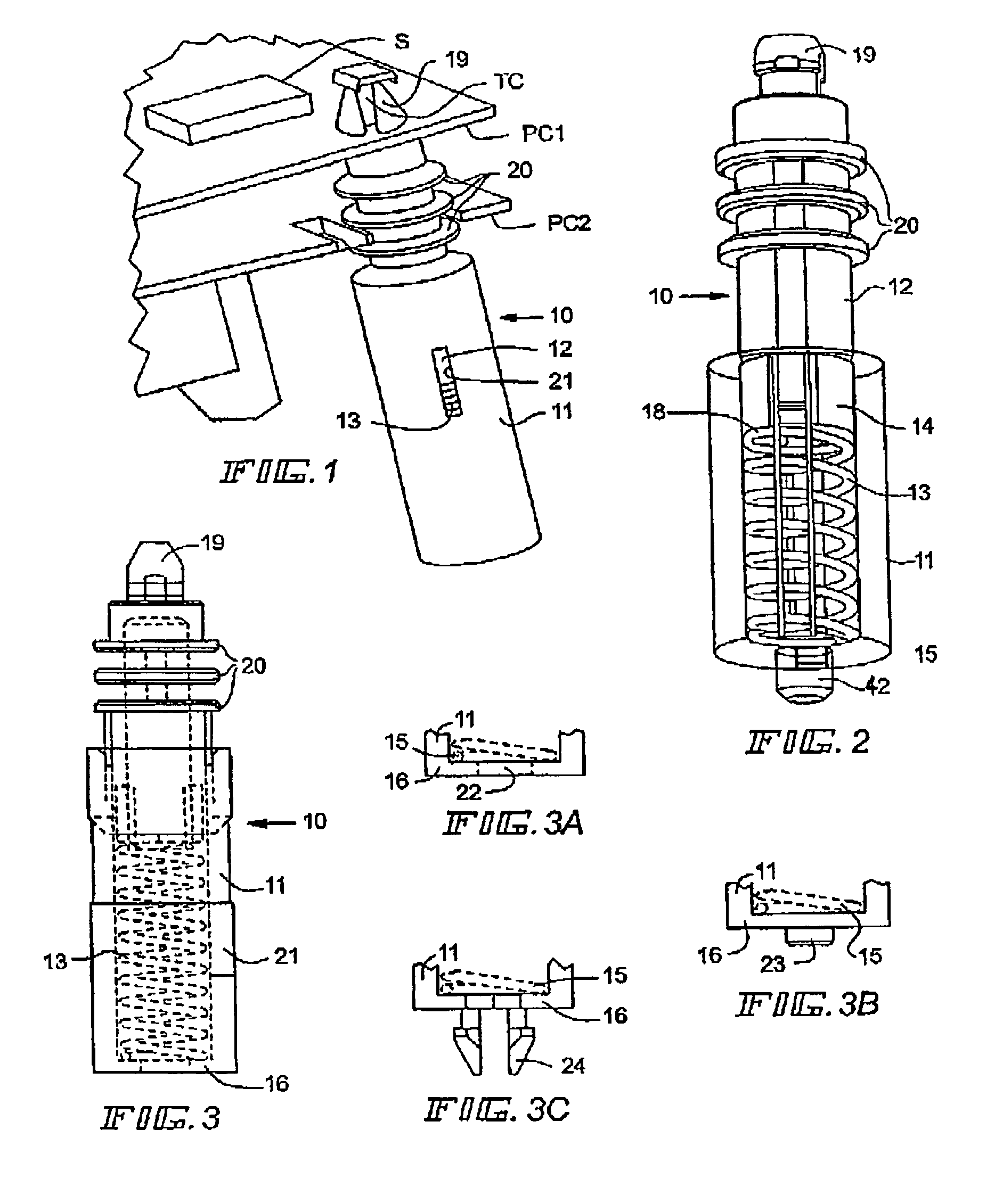
[0026]With reference to FIG. 1, a spring loaded spacer 10 is connected to upper printed circuit board PC1 and lower printed circuit board PC2. Components such as a touch control TC and a light sensor S may be secured on the printed circuit board PC1, as shown. Such a spacer 10 is normally installed on a chassis or underlying panel (not shown), and when installed the spacer is biased away from the chassis and toward the printed circuit boards PC1 and PC2.

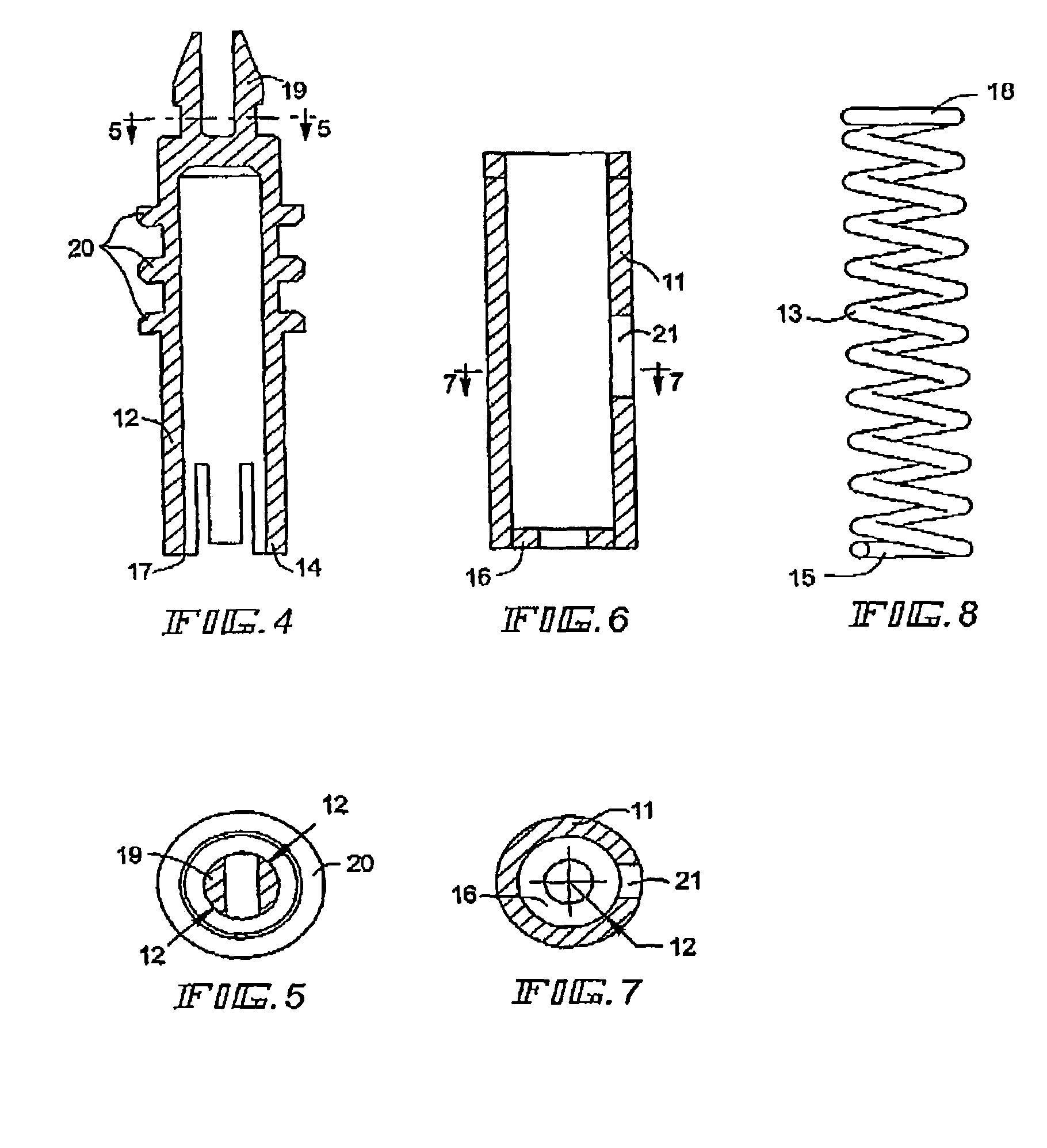
[0027]As shown in FIG. 2, this spring loaded spacer 10 consists of a barrel member 11 having mounting means 42 for connecting the barrel member to an underlying chassis or panel (not shown). The barrel member receives a shank 12 and compression spring 13. The compression spring 13 is installed on a shaft 14 formed on the shank 12 and the spring 13 has a formed end 15 adapted to seat on the bottom 16 of the barrel member 11. Legs 17 are formed in the shank spaced away from the bottom of the shaft 14 to capture the upper end 18 of the ...


PUM


Abstract

A spring loaded spacer for fastening components and control units together with touch control face plates or panels wherein the spacer has a shank portion nested in a barrel portion, one end of the barrel portion being connected to a chassis or the like and its shank portion being connected to one or more printed circuit boards and / or components, and wherein the shank portion is spring loaded within the barrel portion and is adapted to receive one or more printed circuit boards and / or components under tensioned engagement.

Description

[0001]This invention relates to spring loaded spacers, and is more particularly directed to such products, preferably fabricated from plastic and having insulating qualities, and capable of use in fastening systems for components and control units with touch control face plates or panels.BACKGROUND AND SUMMARY OF THE INVENTION[0002]Typically, in conventional touch control assemblies, for example, in oven top touch control panels, a separate spring, a separate spacer and often other parts are connected together with a printed circuit board. These assemblies take a significant amount of time and effort to put together. Parts must be properly sized and substantial facility is required for the assembly. The parts and printed circuit board are critical and assembly error can result in damage to the equipment or lessen the life of the appliance in which they are used. Further such parts are not usually interchangeable, and while many fastening systems may be required for a single applianc...

Claims


Application Information

Patent Timeline
Patent Type & Authority Patents(United States)
IPC IPC(8): F16F9/32
CPCF16F1/128F16F9/54F16F2230/0047H05K1/144H05K2201/042H05K2201/2036Y10T24/42Y10T24/44026B60G11/00B60G11/14F16F9/32
Inventor REISEL, ROBERTCONWAY, IANVOLKER, WILLIM
Owner RICHCO
Why Eureka
Try Eureka