Intramedullary nail

a technology of intramedullary nail and nail, which is applied in the field of intramedullary nail, can solve the problems of nail weakening effect, limited surgeon's choice of screw position, and hole in the bone surface being too close to one another, so as to reduce the propagation of cracks, avoid neurovascular structures, and secure bony fixation

Active Publication Date: 2011-12-27
AO TECH AG
View PDF31 Cites 29 Cited by
  • Summary
  • Abstract
  • Description
  • Claims
  • Application Information

AI Technical Summary

Benefits of technology

[0012]The multiple hole / close spacing intramedullary nail according to the invention can be used for all known applications, i.e., proximal fracture, extreme distal fracture, ankle fusion and correction of deformity and therefore replaces all known nails with one single type, making storage much simpler and less costly. It maximizes the number of screws which can be placed near the tip of the nail, increasing the surface contact area between the hardware and the bone.
[0014]1) it prevents adjacent screws from having their bone cortex holes too close to one another—thereby reducing crack propagation between these bone cortex holes;
[0015]2) it gives the surgeon different anatomical position options for placement of screws to provide more secure bony fixation or to allow avoidance of neurovascular structures; and
[0016]3) it controls angular motion of the fragment with respect to the intramedullary nail by way of a greater possible number of screws, screws in multiple directions, and closer fit of the screws in the holes.
[0022]In order to facilitate a more secure fixation with the interlocking screw having an outer thread at least one of the through holes may be provided with a matching internal thread. This facilitates more secure fixation with the interlocking screw having a matching outer thread.

Problems solved by technology

A disadvantage of the known nails is the fact that the distal holes are unnecessarily far from the distal nail tip which produces a nail-weakening effect, and prevents engagement in very short distal fragments.
A further disadvantage of the known nails having parallel holes spaced closely to one another (i.e., known nail hole spacings equal to 3.5(d)) is the fact that holes in the bone surface are too close to one another.
Still a further disadvantage is that widely spaced parallel or orthogonal holes offer the surgeon limited options in the choice of the position of the screws, such as might be necessary to avoid neurovascular structures.
A further disadvantage of these known nails is the fact that there is an unnecessary loose fit to the hole in the nail by the screws which traverse the nail.

Method used


Image

  • Intramedullary nail
  • Intramedullary nail
  • Intramedullary nail

Examples


Embodiment Construction

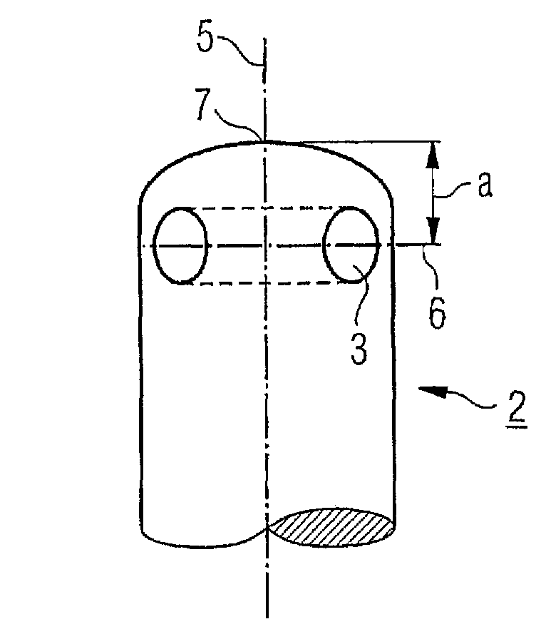
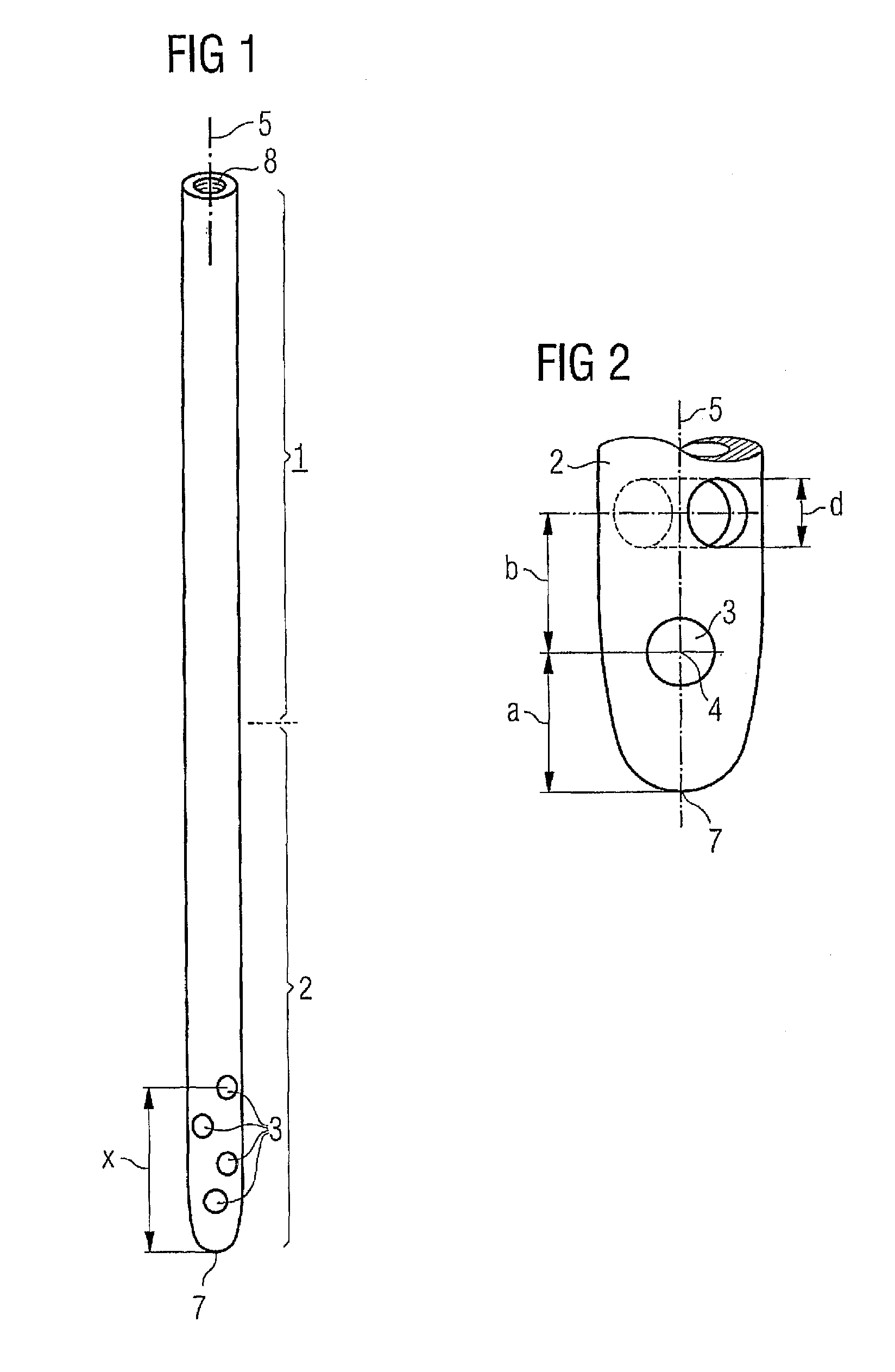
[0038]FIG. 1 shows an intramedullary nail with a solid cross-section having a longitudinal axis 5. The longitudinal axis 5 may be curved along a portion of the nail if the nail itself is curved in that portion. The intramedullary nail further comprises a near end 1 with means 8 consisting of an internally threaded bore for coupling to an insertion device and a far end 2 with a tip 7 for insertion into the intramedullary canal of a long bone. The far end 2 is provided with four traversing through holes 3 with axes 6, all of said through holes 3 being grouped in said far end 2 within a distance x measured from said tip 7 to the axis 6 of the most distant hole 3 (as indicated by the arrow in FIG. 1).

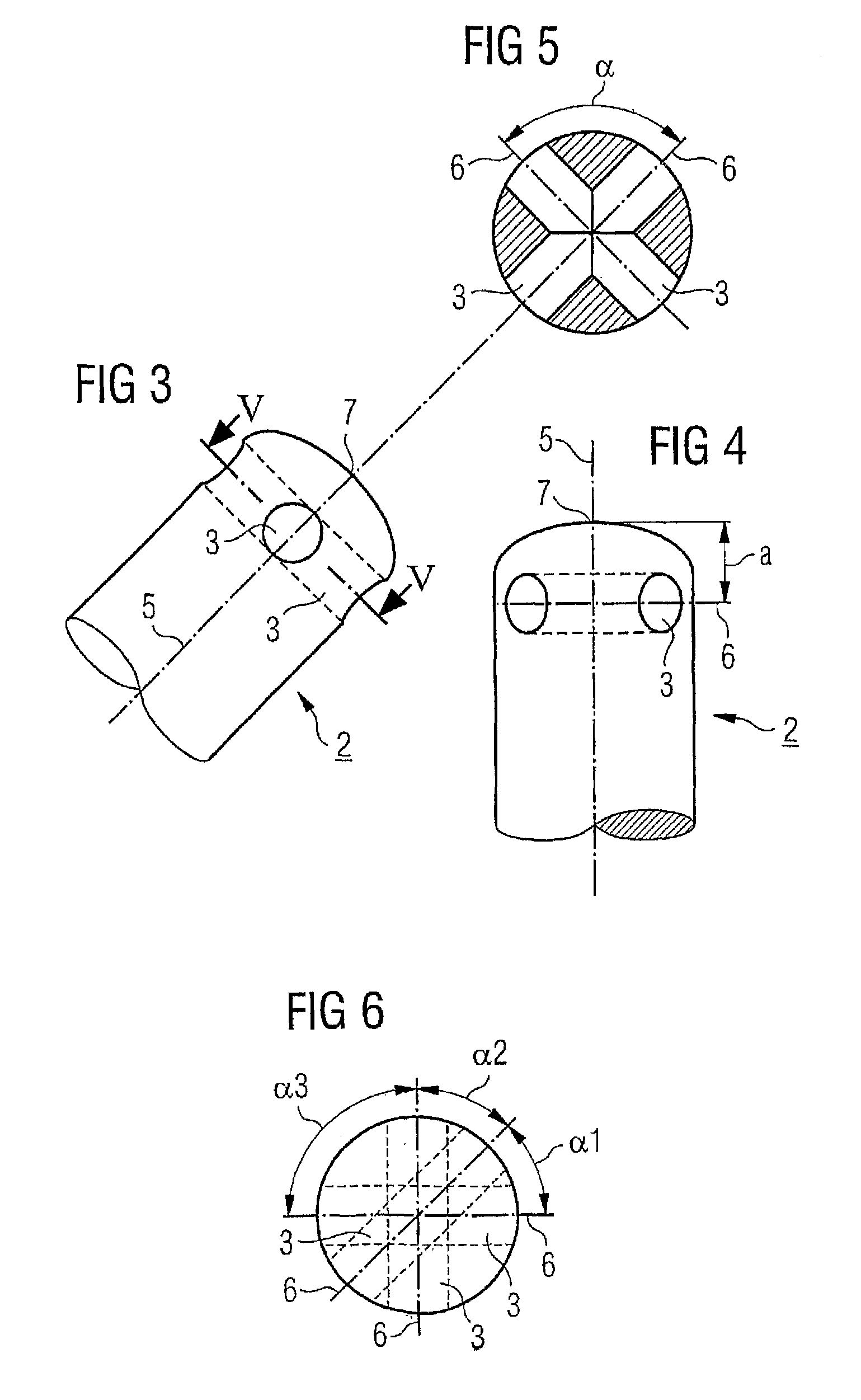
[0039]The projection of the hole axis 6 of said through holes 3 in a plane orthogonal to said longitudinal axis5 (or if the hole axis 6—as shown in the figures—is lying already in an orthogonal plane, the hole axis itself) is such that at least two of said (projected) hole axes 6 are at an ...


PUM


Abstract

The intramedullary nail has a longitudinal axis (5), a near end (1) with means (8) for coupling to an insertion device and a far end (2) with a tip (7) for insertion into the intramedullary canal of a long bone. The far end (2) is provided with at least two traversing through holes (3) with axes (6), all of said through holes (3) being grouped in said far end (2) within a distance x measured from said tip (7) to the axis (6) of the most distant hole (3). The nail is provided with at least a third through hole (3) with axis (6) in said far end (2) which contains the first and second holes (3) and the projection of the hole axis (6) of said through holes (3) in a plane orthogonal to said longitudinal axis (5) is such that at least two of said projected hole axis (6) are at an angle α greater than zero and less than 90° with respect to each other.

Description

FIELD OF THE INVENTION[0001]This invention concerns an intramedullary nail and, more particularly, an intramedullary nail having a plurality of transverse holes extending through a distal end of the nail.BACKGROUND OF THE INVENTION[0002]Such a nail is known from German patent publication DE-C-3 244 243 to ENDER, which discloses a rigid intramedullary nail having two through holes at the distal end of the nail and whose direction is not parallel and not orthogonal and which is further defined in the specification to be at an acute angle, e.g., of 10° or 60°.[0003]A further nail is known from U.S. Pat. No. 5,041,115 to FRIGG et al., which discloses an intramedullary nail having three through holes at the distal end of the nail which are disposed at 90° to each other.[0004]A disadvantage of the known nails is the fact that the distal holes are unnecessarily far from the distal nail tip which produces a nail-weakening effect, and prevents engagement in very short distal fragments.[0005]...

Claims


Application Information

Patent Timeline
Patent Type & Authority Patents(United States)
IPC IPC(8): A61B17/58A61F2/30A61B17/72
CPCA61B17/7233A61B17/72
Inventor MARTIN, DANIEL L
Owner AO TECH AG
Why Eureka
Try Eureka