Microfluidic arrangement for metering of liquids

a microfluidic arrangement and liquid technology, applied in the field of microfluidic arrangement, can solve problems such as the possibility of complicatedness

Active Publication Date: 2011-12-27
BOEHRINGER INGELHEIM MICROPARTS
View PDF17 Cites 1 Cited by
  • Summary
  • Abstract
  • Description
  • Claims
  • Application Information

AI Technical Summary

Benefits of technology

[0004]Against the background of these disadvantages of the arrangements from the art, an object of the invention is to propose a microfluidic arrangement in

Problems solved by technology

One disadvantage in the existing microfluidic arrangements for metering and separating by means of a gaseous phase is that to produce the negative pressure or the overpressure (exhaust or blow away) for separation of the first from the s

Method used


Image

  • Microfluidic arrangement for metering of liquids
  • Microfluidic arrangement for metering of liquids
  • Microfluidic arrangement for metering of liquids

Examples


second embodiment

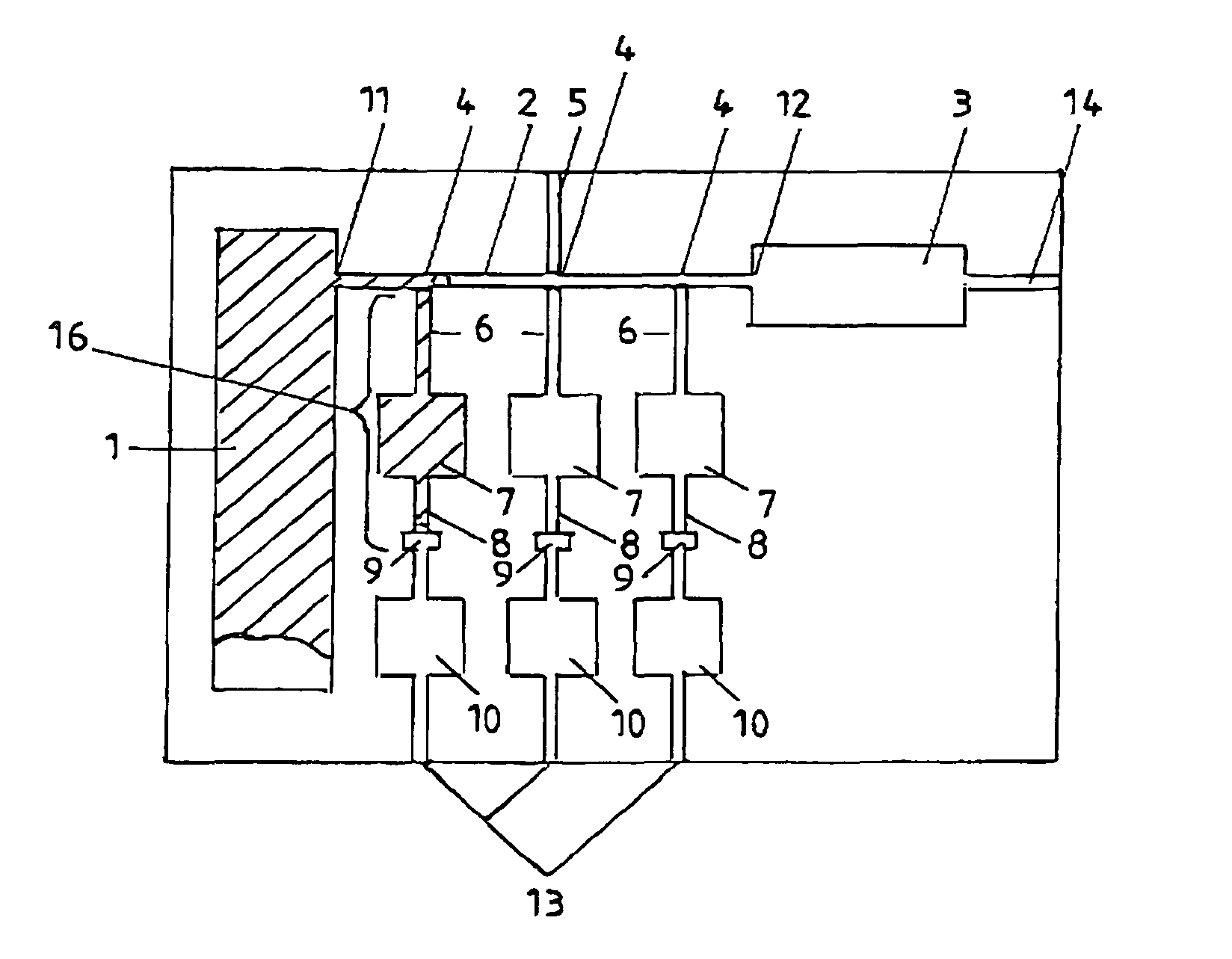
[0032]The liquid contained in the defined volume of the second channel system 6, 7, 8 can then be transported into the third channel system 10 after the action of the capillary stop 9 has been neutralized. This is described in greater detail using FIG. 7 for the

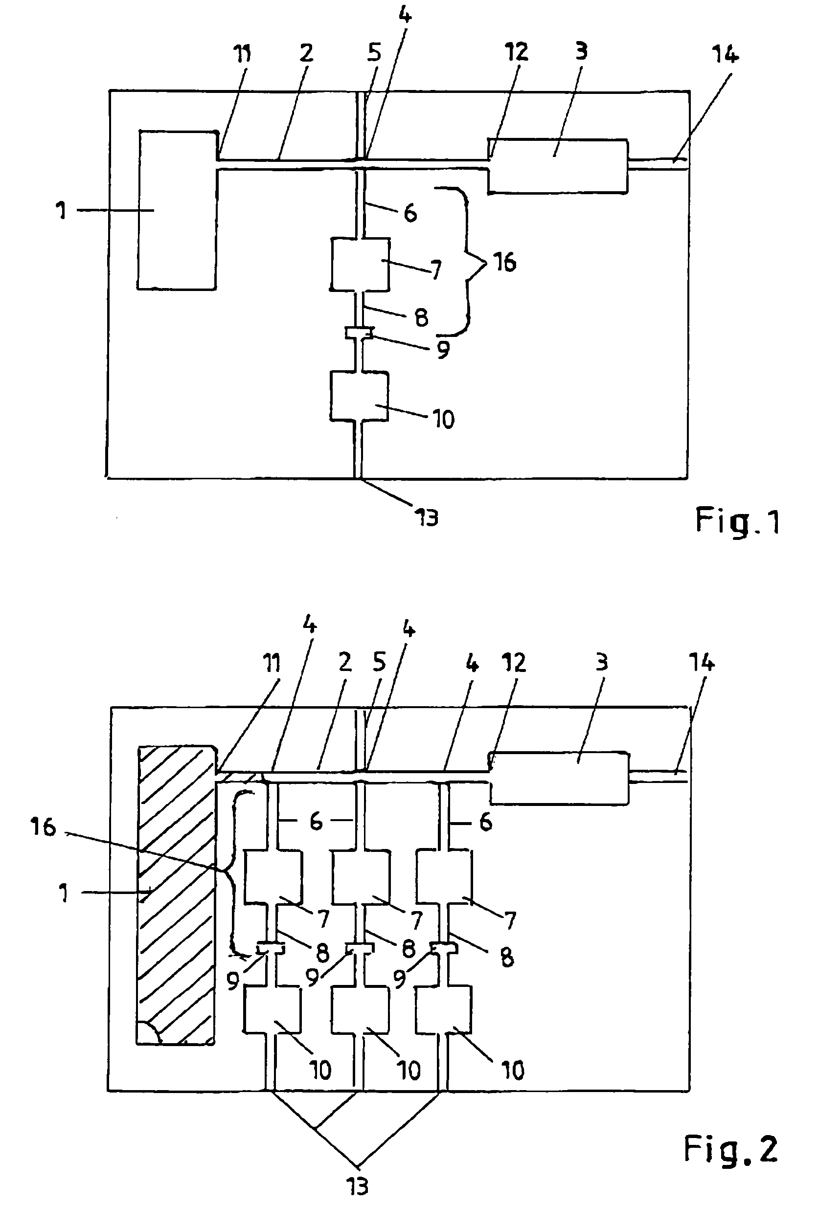
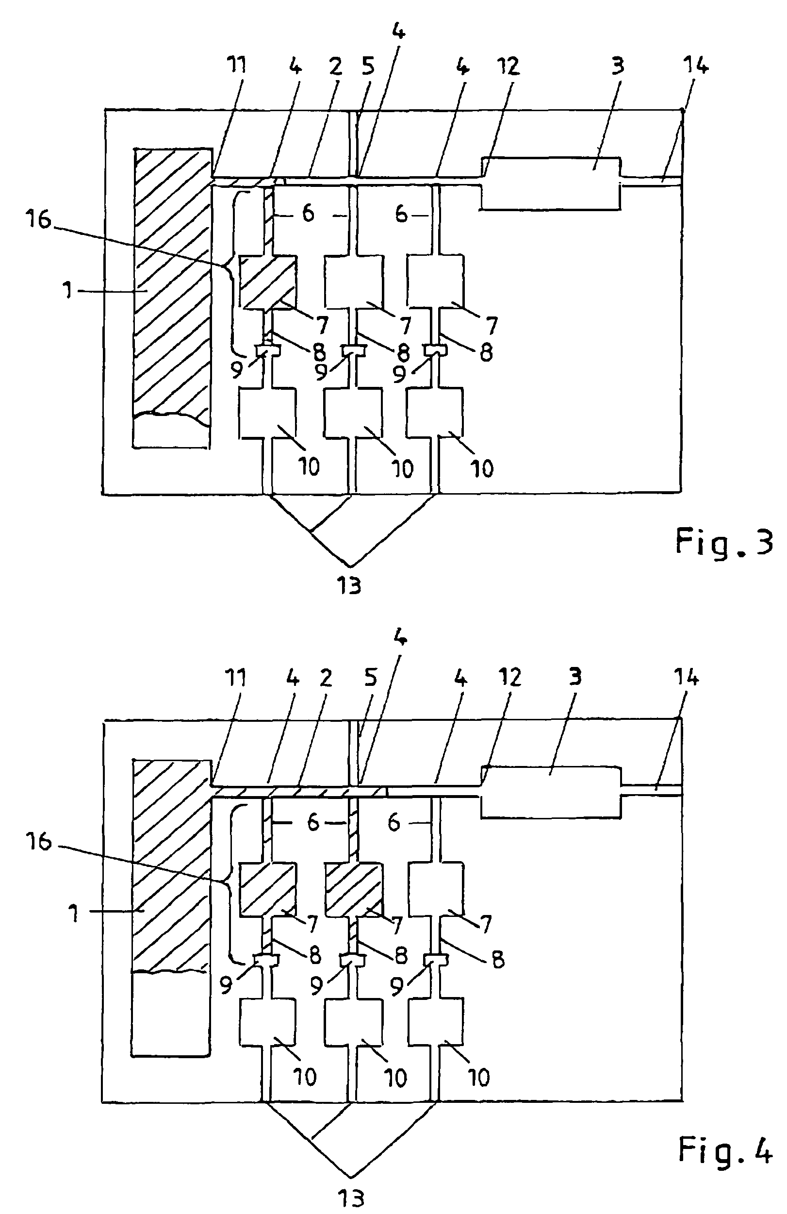
[0033]The second embodiment, which is shown in FIGS. 2 to 6, corresponds in large parts to the first embodiment shown in FIG. 1. Therefore the same components of the microfluidic arrangements as shown in FIG. 1 and FIG. 2 to FIG. 6 are provided with the same reference numbers. The first embodiment and the second embodiment differ simply in that in the second embodiment there are several, specifically three second channel systems 16 and three third channel systems 10. Moreover the inlet reservoir 1 is made distinctly larger, the volume of the inlet reservoir 1 here also being less than or equal to the sums of the volumes of the second channel systems 16 and of the second outlet reservoir 3.

first embodiment

[0034]The three second channel systems 16 branch off at the branch points 4 in the direction from the inlet 11 to the outlet 12 in succession from the channel of the first channel system 2. The first sections 6 of the second channel system 16 are each connected to the branch points 4. These first sections 6 of the channel system then discharge, as already known from the first embodiment, into a second section 7 which then discharges into the third section 8. The third section 8 of the second channel system 16 then ends at one capillary stop 9 at a time. A third channel system 10 which discharges into one second outlet 13 at a time is then connected downstream of the capillary stop 9.

[0035]If at this point in the second embodiment as shown in FIG. 2 to FIG. 6 the inlet reservoir 1 is filled with liquid from the outside, this liquid enters the first channel system 2 at the inlet 11. As a result of the acting capillarity the liquid is drawn into the channel of the first channel system ...


PUM


Abstract

The invention relates to a microfluidic arrangement for metering one or more first metered amounts of liquid (A) and for separating the latter from a second amount of liquid (B), having the following features: the arrangement has a first channel and one or more second channels; the first channel has one inlet and one outlet; in the area of the outlet the arrangement has a capillarity, which is greater than or equal to the capillarity in the area of the inlet; the one or more second channels branch off from the first channel at one or more branch points; the one or more second channels have a greater capillarity than the first channel at the branch points; and the one or more second channels have a predetermined volume. In the arrangement as depicted in the invention a liquid is transported in the first channel from the inlet to the outlet. At the branch points one portion of the liquid at a time enters the one or more second channels and fills them completely with the first metered amounts of liquid (A). The portion of the liquid remaining after the last branch point in the first channel emerges as the second amount of liquid via the outlet from the first channel. The amounts of liquid (A) metered in the one or more second channels are separated from the remaining amount of liquid (B) by a gas, which is located in the first channel after filling all one or more second channels.

Description

BACKGROUND OF THE INVENTION[0001]This invention relates to a microfluidic arrangement for metering and separating one or more first metered amounts of liquid from a second amount of liquid.[0002]The existing art discloses various such microfluidic arrangements. These microfluidic arrangements are used for example for metering and injecting liquids for wet chemical, biochemical and diagnostic analyses. Here, among others, volumetric elements are filled with a defined first liquid amount. This defined amount of liquid is separated from a excess second amount of liquid. Currently the separation of the excess amount of liquid from the metered amount of liquid takes place generally by mechanical elements or by a gaseous phase. The gaseous phase can be obtained by exhausting the excess amount of liquid. It is likewise possible for the excess amount of liquid to be “blown away” from the metered amount of liquid by means of a pressure surge.[0003]One disadvantage in the existing microfluidi...

Claims


Application Information

Patent Timeline
IPC IPC(8): G01N1/18B01J4/00B01L3/00G01F11/28G01N1/00G01N1/10G01N37/00
CPCB01L3/5027B01L3/502738B01L3/502784B01L2200/0605B01L2300/0861B01L2400/0406B01L2400/0487B01L2400/0688G01F11/28Y10T436/2575Y10T436/25375
Inventor PETERS, RALF-PETERBLANKENSTEIN, GERTOSTERLOH, DIRK
Owner BOEHRINGER INGELHEIM MICROPARTS
Why Eureka
Try Eureka