
Read/write tip, head and device, and use thereof, and method for manufacturing same

a technology of head and device, which is applied in the field of read/write tip and the head of read/write device, to achieve the effect of improving the autonomy of such sources

Inactive Publication Date: 2011-10-18
CENT NAT DE LA RECHERCHE SCI
View PDF4 Cites 4 Cited by
  • Summary
  • Abstract
  • Description
  • Claims
  • Application Information

AI Technical Summary

Benefits of technology

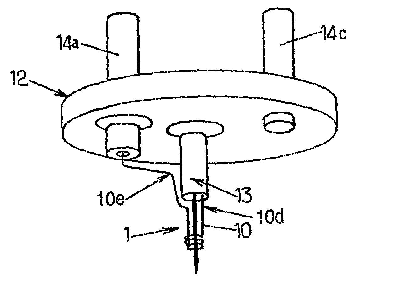
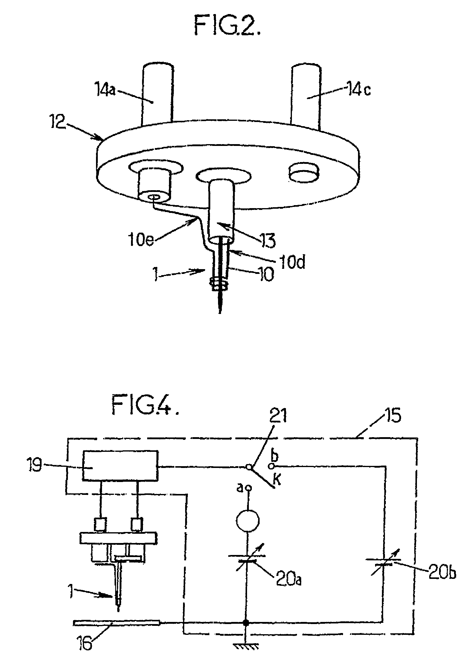
[0018]Thanks to these arrangements, one single tip can be used both as the tip of a tunnel effect microscope, for implementing an operation of reading the characteristics of the surface of the substrate, and as a writing tip, to form the surface of the substrate, as a source of liquid or solid metal ions. Such a tip has the advantage of being able to alternate easily between writing and reading stages, which is useful in practice for being able to locate easily the place where the writing is to be carried out, without having to use an external microscopy system.
[0020]When writing in liquid-metal ion emission mode, the fluidity of the metal covering the core makes it possible to retain a tip geometry which will still be suitable for a subsequent reading.
[0021]After writing in solid metal ion emission mode (at a lower temperature), a local erosion effect can be obtained at the tip. By means of the heat transfer device, a regeneration operation of the tip can be implemented, to cause it to recover its initial geometrical configuration, suitable for the reading mode.
[0072](z1) the core is toughened by chemical etching, to increase the capillarity of the core to the electrically conductive material by forming longitudinal micro-channels therein,

Problems solved by technology

However, the autonomy of such sources remains relatively limited, due to the solid character of the material to be evaporated when it is present on the needle.

Method used


Image

  • Read/write tip, head and device, and use thereof, and method for manufacturing same
  • Read/write tip, head and device, and use thereof, and method for manufacturing same
  • Read/write tip, head and device, and use thereof, and method for manufacturing same

Examples


Embodiment Construction

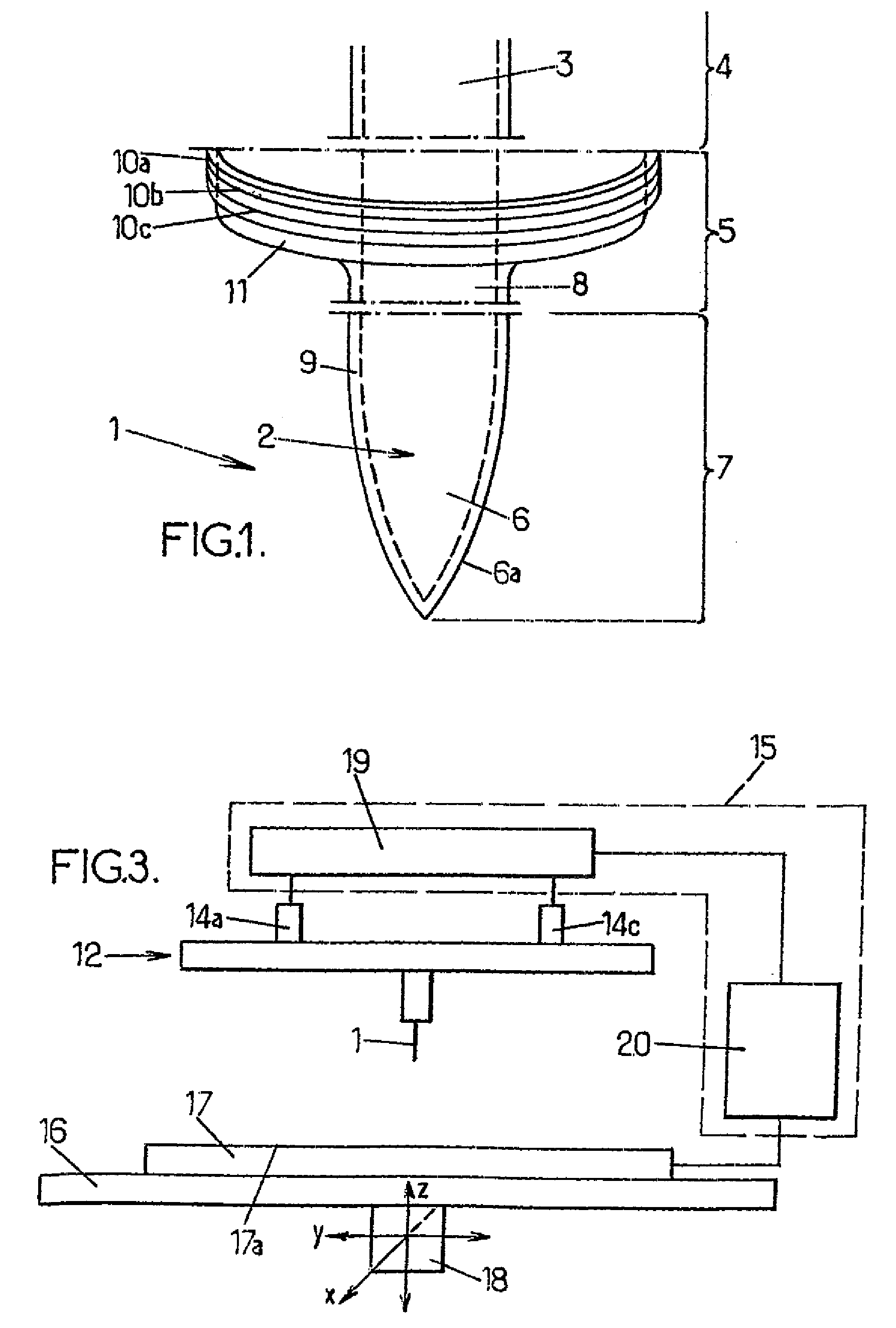
[0088]FIG. 1 (not to scale, for easier understanding) shows part of a read / write tip. This tip 1 is generally in the shape of a needle 2 having an approximately cylindrical body 3 extending both in a proximal portion 4 and a median portion 5 of the tip, and a pointed end 6 extending in a distal portion 7 of the tip in an extension of the body 3. The external geometrical configuration of the pointed end 6, which extends over a few tenths of millimeters is that of a tip of a tunnel effect microscope. The terminal radius of curvature of the tip is comprised between approximately 0.1 and 2 micrometers, preferably between 0 3 and 1 micrometer, as measured by scanning microscopy. Thus, the external surface 6a of the pointed end 6 will be given the full geometrical configuration suitable for use of the read / write head as a tunnel-effect microscope needle

[0089]The needle 2 comprises a long tapered core 8 of a refractory material, such as for example tungsten, covered by a fine layer 9 of an...


PUM

PropertyMeasurementUnit
diameteraaaaaaaaaa
diameteraaaaaaaaaa
sizeaaaaaaaaaa

Abstract

The invention concerns a reading / writing tip configured in the shape of a needle consisting of a core of refractory material covered with a coating of electrically conductive material, and having an outer microscope needle geometry by tunnel effect, to obtain an information concerning a surface through tunnel-effect microscopy The needle emits a charged particle from the layer of electrically conductive material, to form the surface. The tip comprises a reservoir capable of being liquefied to flow along the tip.

Description

CROSS-REFERENCE TO RELATED APPLICATION[0001]This application is a U.S. National Stage Application of PCT Application No. PCT FR2006 / 002243, filed on Oct. 5, 2006, which claims priority under the Paris Convention to French Patent Application No FR 05 10793, filed on Oct. 21, 2005.FIELD OF DISCLOSURE[0002]The present invention relates to the tips and the heads of read / write devices, to read / write devices, and to methods for manufacturing such devices.BACKGROUND OF THE DISCLOSURE[0003]The article “An improved gallium liquid-metal ion source geometry for nanotechnology”, Van Es et al, Microelectronic Engineering 73-74, (2004); 132-138 describes an example of a liquid-metal ion source. Such a source generally comprises a tip configured in the shape of a needle formed of a core of a refractory material (tungsten, in this article) partially covered with a layer of electrically conductive material (gallium, in this article),[0004]said needle having a portion for connection to an electrical ...

Claims


Application Information

Patent Timeline
Patent Type & Authority Patents(United States)
IPC IPC(8): G11B9/00G01Q10/00G01Q60/10G01Q60/16G01Q70/16G01Q80/00
CPCG11B9/1409G11B9/149B82Y10/00G01Q80/00
Inventor GIERAK, JACQUESMARTROU, DAVID
Owner CENT NAT DE LA RECHERCHE SCI
Learn More