
Writing instrument containing a granular material in the ink chamber

a technology of ink chamber and granular material, which is applied in the field of writing instruments, can solve the problems of difficult reproducible production of ink in large runs, difficult sintering step, and considerable additional cost of the pen, and achieve the effect of improving the capillarity of the ink

Active Publication Date: 2013-01-08
SOC DITE SOC BIC
View PDF12 Cites 3 Cited by
  • Summary
  • Abstract
  • Description
  • Claims
  • Application Information

AI Technical Summary

Benefits of technology

[0007]One aim of the embodiments of the present invention is to improve the capillarity of the ink in the reservoir of the writing instrument in order to obtain an even supply of ink to the nib, while allowing the reservoir to be filled rapidly during the manufacture of the instrument.
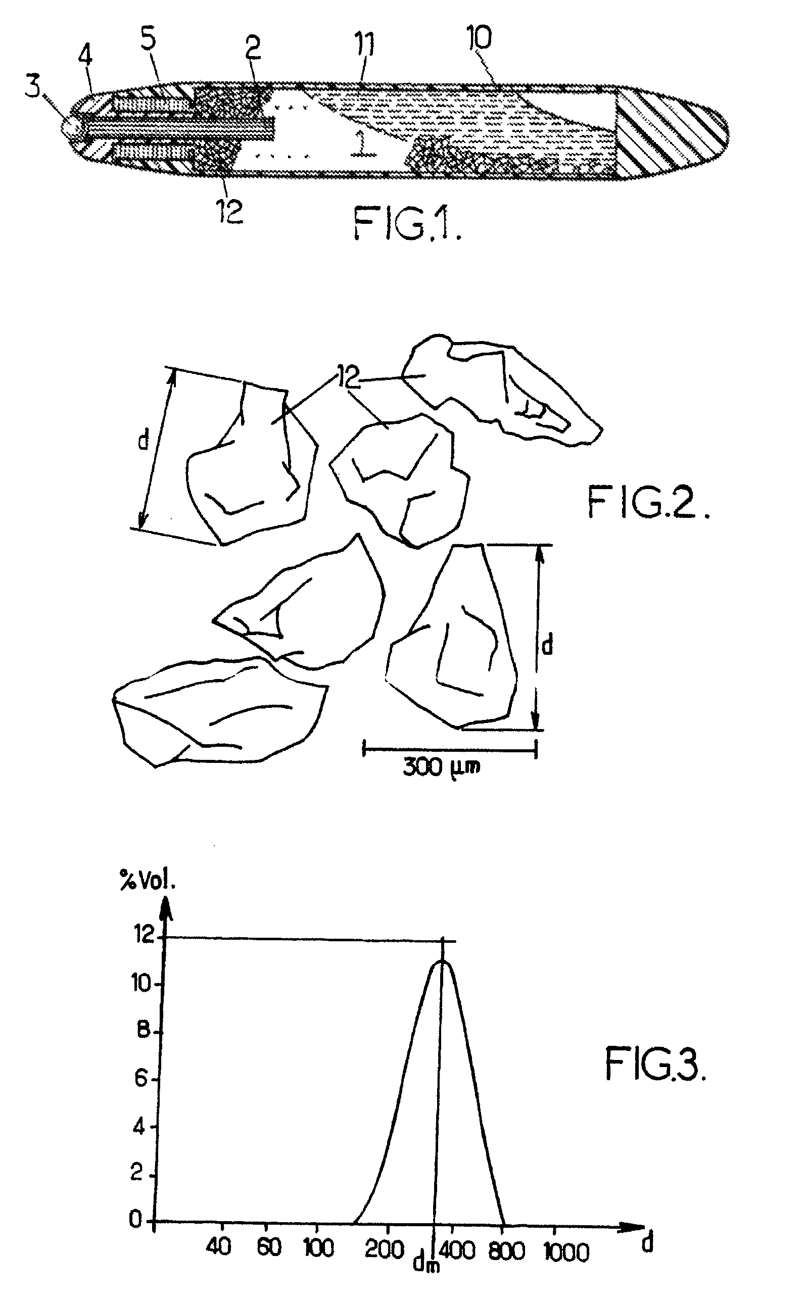
[0009]The presence of angles and sharp edges on the grains must contribute to a capillary behavior of the ink in the reservoir which provides the writing tip with an even supply of the ink, more than the arrangement of the grains amongst themselves. These angles and sharp edges result from the external shape of the grains. These are therefore reliefs having dimensions of the same order of magnitude as the apparent dimension d, or the granulometry, of a grain in question, that is to say from a few tenths to a few hundredths of its apparent dimension d. The ink flow through the tip is then constant. In addition, a considerable proportion of the ink initially contained in the reservoir may be restored during a prolonged use of the writing instrument. It is supposed that these large angles and sharp edges favorably modify the dynamics of the fluids of the ink between the grains, and even the physical-chemical interactions between the ink and the grains, which would improve the return of the ink contained in the capillary spaces formed between the grains. Additionally, the capillary spaces between the grains have shapes and volumes that are substantially variable because of the irregular shape of the grains, which would have a favorable effect on regulating the flow of ink that the reservoir delivers in its totality.
[0010]The presence of angles and sharp edges also limits a consolidation or compaction of the grains in the reservoir, when the writing instrument is kept immobile in a fixed position. The operation of the writing instrument is then relatively unaffected by prolonged storage of the instrument without agitation of the grains.
[0011]The presence of the separate grains in the reservoir, which are submerged in the ink, also makes it possible to attenuate increased pressures in the ink that are likely to be caused by impacts on the writing instrument. Leaks of ink through the writing tip that such impacts could cause are then reduced or prevented.
[0012]Since the grains are separate, that is to say that they are not linked together, they may be simply poured into the reservoir even if the shape of the latter is complex, and the ink can then be injected into the reservoir by means of a hollow needle. For example, the needle may be sunk into the grains to the bottom of the reservoir, and then the ink is expressed from the needle between the grains during a gradual retraction of the needle. A rapid and uniform filling of the reservoir can then be easily obtained.
[0013]Finally, the use of separate grains allows a good ventilation of the ink reservoir. A device for venting the reservoir that is particularly simple may then be used. In particular, the use of a simplified venting device makes it possible to design and produce writing instruments that have complex or original shapes.

Problems solved by technology

A sintered material that has a determined open porosity is difficult to produce in large runs in a reproducible manner.
The sintering step then generates a considerable additional cost for the pen.
In addition, filling the reservoir with the ink is made difficult, because the ink is slow to penetrate the interstices of the sintered granular material.
Furthermore, when the granular material has to be distributed in a controlled manner in the form of separate grains in the reservoir, the grains must be placed in the reservoir in several steps, which represents an awkward and lengthy step in the manufacture of the pen.
These disadvantages explain why no solution of this type is applied industrially in the present day.
In these conditions, the capillarity of the reservoir of the writing instrument relative to the ink is not significantly improved.

Method used


Image

  • Writing instrument containing a granular material in the ink chamber
  • Writing instrument containing a granular material in the ink chamber

Examples


Embodiment Construction

[0033]It is understood that the dimensions of the various portions of the writing instrument that are shown in FIG. 1 do not correspond either to real dimensions or to real dimension ratios. In particular, these dimensions may be adapted to obtain a writing instrument that has a greater ink content, or to produce a writing instrument that has a pocket format.

[0034]As an example, the writing instrument shown in FIG. 1 is of the “roller pen” type. It comprises an ink reservoir 1 that is limited by a side wall 10, a connector 2, and an ink roller 3 which forms the writing tip. The ink roller 3 is held, while remaining free to rotate, by the mount 4 that is attached to an anterior end of the reservoir 1. The connector 2 allows a flow of the ink 11 that is contained in the reservoir 1 toward the ink roller 3. It may consist of a cylindrical assembly of fibers aligned longitudinally and designed to be impregnated by the ink 11. If necessary, one end of the connector 2 may protrude into th...


PUM


Abstract

A writing instrument that includes an ink reservoir and a writing tip fluidly connected to the reservoir and through which the ink comes out during use of the instrument. The reservoir contains, in addition to the ink, grains that are separate and that may have angles and sharp edges of dimensions that are significant relative to an apparent dimension (d) of the grains.

Description

CROSS-REFERENCE TO RELATED APPLICATIONS[0001]This application is a national stage application of International Application No. PCT / FR2007 / 000062, filed on Jan. 12, 2007, which claims priority to French Patent Application No. 06 00335 filed on Jan. 13, 2006, the entire contents of both applications being incorporated herein by reference.BACKGROUND OF INVENTION[0002]1. Field of Invention[0003]The embodiments of the present invention relate to a writing instrument that incorporates a granular material in its ink reservoir.[0004]2. Description of the Related Art[0005]An ink reservoir design of this type is known from U.S. Pat. No. 2,528,408. Specifically, this document discloses a nib pen whose ink reservoir is provided with a granular material. The structure of this material gives it a capillarity versus the ink that is suitable for obtaining a steady supply of ink to the nib. However, to obtain this capillarity, the granular material is sintered or has a distribution of grains inside ...

Claims


Application Information

Patent Timeline
Patent Type & Authority Patents(United States)
IPC IPC(8): B43K5/00
CPCB43K5/02B43K7/02B43K7/08B43K7/10B43K8/03B43K8/06
Inventor BEDHOME, VINCENTLANGE, DIDIERROLION, FRANCK
Owner SOC DITE SOC BIC
Learn More