Self adjusting stereo camera system

a stereo camera and self-adjusting technology, applied in the field of stereo camera systems, can solve the problem of no improvement in spatial resolution during operation, and achieve the effect of reducing the operational range of the system and improving spatial resolution

Inactive Publication Date: 2011-12-27
KONINKLIJKE PHILIPS ELECTRONICS NV
View PDF37 Cites 41 Cited by
  • Summary
  • Abstract
  • Description
  • Claims
  • Application Information

AI Technical Summary

Benefits of technology

[0008]Therefore it is an object of the present invention to provide a stereo camera system which improves spatial resolution during the mode of operation of the stereo camera system but which does not decrease the operational range of the system.

Problems solved by technology

However, in the prior art stereo camera systems, these parameters are adjusted before use and remain the same throughout the period of operation, thus, no improvement in spatial resolution is made during operation.

Method used


Image

  • Self adjusting stereo camera system
  • Self adjusting stereo camera system
  • Self adjusting stereo camera system

Examples


Embodiment Construction

[0020]Although this invention is applicable to numerous and various types of stereo imaging means for producing a stereo image, it has been found particularly useful in the environment of stereo camera systems having fixed mirrors or two or more cameras. Therefore, without limiting the applicability of the invention to stereo imaging means having fixed mirrors or two or more cameras, the invention will be described in such environment.

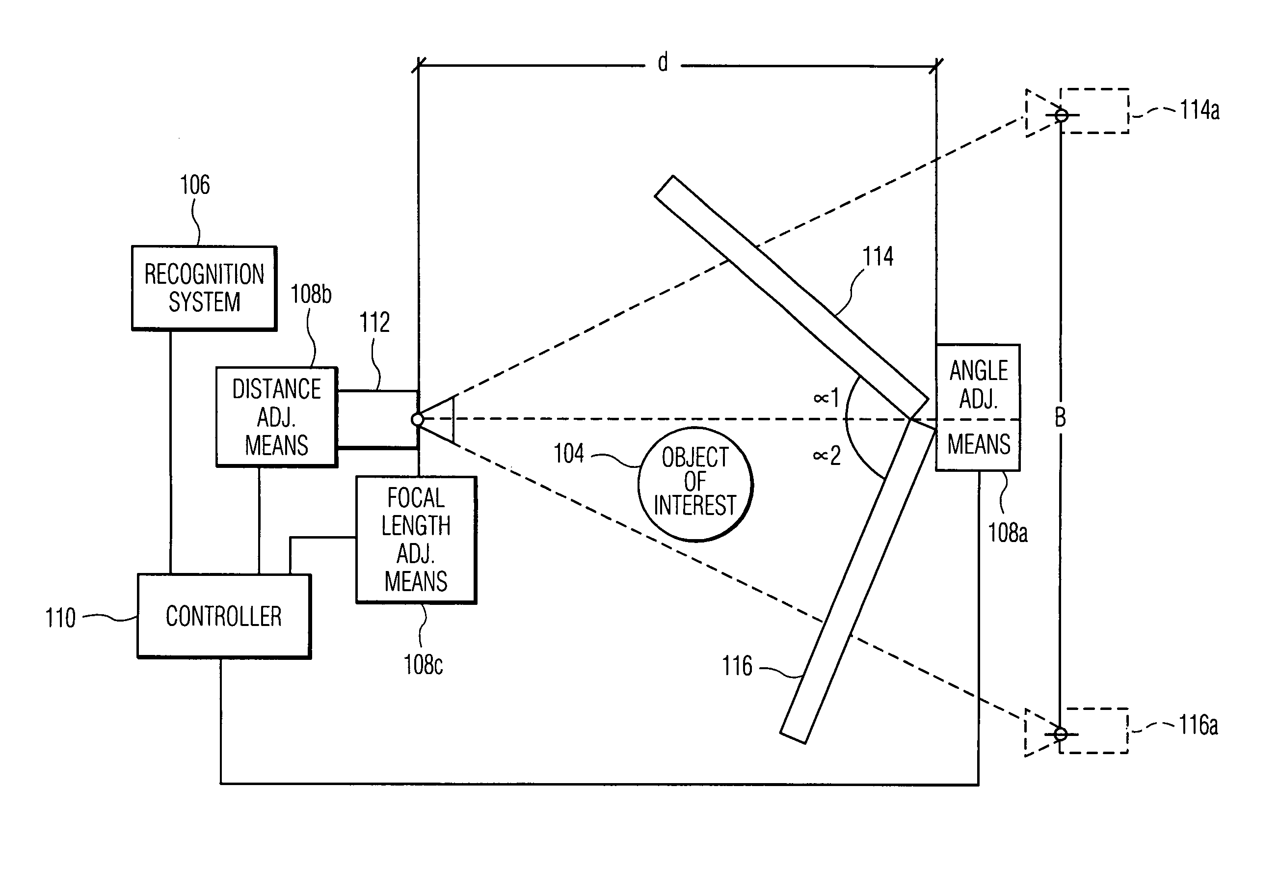
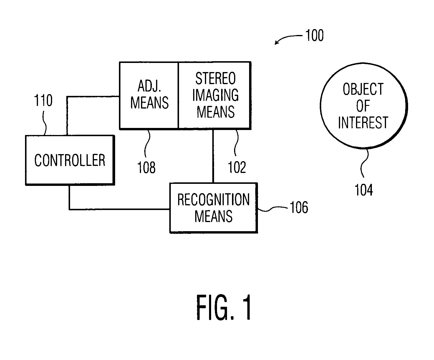
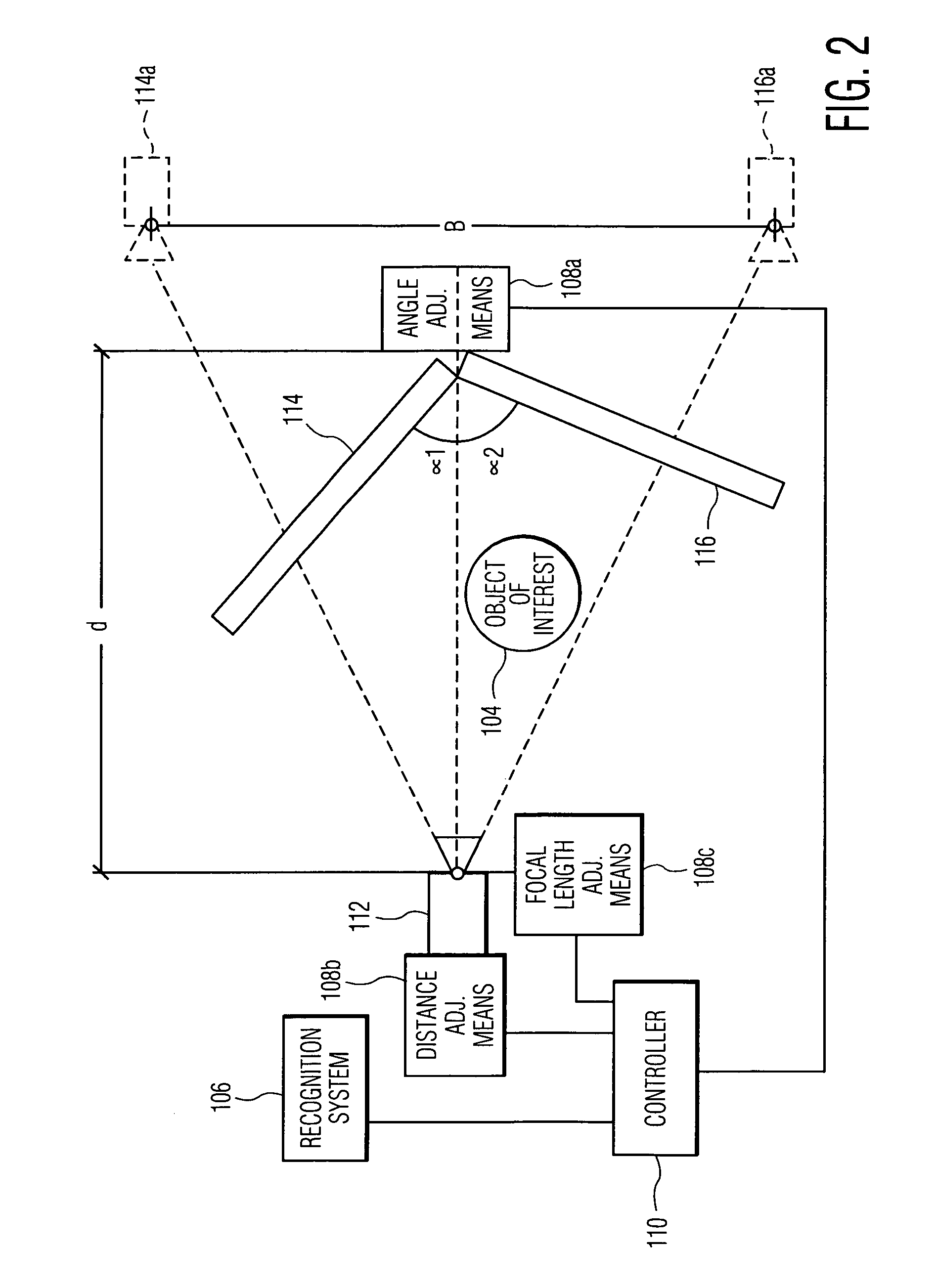
[0021]Referring now to FIG. 1, there is illustrated a schematic of a stereo camera system, generally referred to by reference numeral 100. The stereo camera system comprises a stereo imaging means 102 for outputting at least one stereo image of an object of interest 104 located in the field of view of the stereo imaging means 102. A recognition means locates the object of interest 104 and calculates the distance of the object of interest 104 from the stereo imaging means 102 and / or the size of the object of interest 104. An adjusting means 108 is provi...


PUM


Abstract

A stereo camera system including: a stereo imaging system such as two or more cameras or a camera and a set of angled mirrors, for outputting at least one stereo image; a recognition system for locating an object of interest in the field of view of the stereo imaging system and at least one of a distance of the object of interest from the stereo imaging system and the size of the object of interest; and an adjustor for automatically changing at least one system parameter which affects the spatial resolution of the object of interest based on at least one of the located distance of the object of interest from the stereo imaging system and the size of the object of interest.

Description

BACKGROUND OF THE INVENTION[0001]1. Field of the Invention[0002]The present invention relates generally to stereo camera systems and, more particularly, to stereo camera systems which automatically self adjust to increase the resolution of an object of interest based on a detected distance of the object of interest from the camera and / or a detected size of the object of interest.[0003]2. Prior Art[0004]Various imaging systems have been developed in the art to produce stereoscopic or 3D images. These systems generally consist of a method for creating two images as seen from a different perspective and means for displaying the images so that one eye sees one perspective of the image and the other eye sees a different perspective of the image to produce a 3D image.[0005]One method is based on the use of separate spaced apart optical means to produce two perspectives of the same image. The images are displayed side by side, such as on film or on a monitor. Means are provided so that the...

Claims


Application Information

Patent Timeline
Patent Type & Authority Patents(United States)
IPC IPC(8): H04N13/02H04N13/239
CPCH04N13/0217H04N13/0239H04N13/0296H04N13/296H04N13/218H04N13/239H04N23/00
Inventor BRODSKY, TOMASLEE, MI-SUENCOHEN-SOLAL, ERIC
Owner KONINKLIJKE PHILIPS ELECTRONICS NV
Why Eureka
Try Eureka