Medical image diagnosis apparatus and the control method thereof

a technology of image diagnosis and control method, which is applied in the field of medical image diagnosis apparatus and the control method thereof, can solve the problems of inaccuracy in diagnosis, difficulty in defining the location of the object p with a high degree of accuracy in relation to the location pinpointed from the image, and concern about the deterioration of treatment planning

Active Publication Date: 2011-12-27
TOSHIBA MEDICAL SYST CORP
View PDF87 Cites 14 Cited by
  • Summary
  • Abstract
  • Description
  • Claims
  • Application Information

AI Technical Summary

Benefits of technology

This invention is intended to provide a medical image diagnosis apparatus and its control method that can correct the displacement of the patient table without implementing a major alteration to the hardware configuration of the apparatus.
As described above, according to the first aspect, because the effect of deflection from the patient table can be corrected based on the image of the patient table in a state in which the object is not placed on the patient table and the image of the patient table in a state in which the object has been placed on the patient table, unlike the conventional method, the effect of deflection from the patient table can be corrected without significantly altering the device.
As described above, according to the second aspect, because the effect of deflection from the patient table (tilt of tomographic images) can be corrected based on the image of the patient table in a state in which the object is not placed on the patient table and the image of the patient table in a state in which the object has been placed on the patient table, unlike the conventional method, the effect of deflection from the patient table can be corrected without significantly altering the device.
As described above, according to the third aspect, because the effect of deflection from the patient table can be corrected based on the image of the patient table in a state in which the object is not placed on the patient table and the image of the patient table in a state in which the object has been placed on the patient table, unlike the conventional method, the effect of deflection from the patient table can be corrected without significantly altering the device.
As described above, according to the fourth aspect, because the effect of deflection from the patient table (tilt of tomographic images) can be corrected based on the image of the patient table in a state in which the object is not placed on the patient table and the image of the patient table in a state in which the object has been placed on the patient table, unlike the conventional method, the effect of deflection from the patient table can be corrected without significantly altering the device.

Problems solved by technology

As described above, making an image diagnosis using a less-accurate reconstructing image different from the cross-section at the planning stage of the scan may lead to inaccuracy in diagnosis.
For example, there is concern about deterioration of treatment planning for radiotherapy whereby radiation is delivered to an affected area such as a tumor.
When using an image containing a displacement caused by patient table deflection, it is relatively easy to pinpoint the location of a lesion in the image, but it is difficult to specify the location in the object P with a high degree of accuracy in relation to the location pinpointed from the image, because a state in which the object is placed on the patient table of the object P is different from a state in which the object is placed on the patient table of the object P during the treatment planning stage (in general, the object P is placed with his / her body axis being horizontal).
When dealing with the above mentioned problem of the displacement of the patient table with the conventional medical image diagnosis apparatus described above, the following inconvenience will occur.
On the other hand, considering the price of the apparatus, etc., it would be a heavy burden for the user to purchase a new apparatus with such construction preapplied.
However, it is not easy to control such movements accurately.
In addition, when applying the construction of changing the angle of tilting the patient table, the patient as the object may feel uncomfortable as the tilt angle of the object is also changed accordingly.
When applying the former assumption, the patient table must be strengthened, but if the strength of the patient table is enhanced, other problems may arise, including reduction of sensitivity to gamma ray detection due to the increased absorption of gamma rays by the patient table as described in Japanese Unexamined Patent Application Publication No. 2005-291814.
On the other hand, when applying the latter assumption, multiple sensors should be installed on the patient table which also causes other problems such as increase in cost, complex control and more maintenance.
Furthermore, assuming that the direction of the displacement of all of the each point is parallel, a problem occurs in that the tilt condition of the patient table cannot be accurately detected.
However, the change in the angle of tilting the patient table between the sensors cannot be detected, because only the tilt angle of the line connecting the sensors can be calculated according to the computation method of the document.
Therefore, it is difficult to ensure the accuracy of the irradiated site.
Moreover, because the construction described in Japanese Unexamined Patent Application Publication No. 2005-291814 is for matching an image for nuclear medicine with an image of an X-ray CT, it cannot be applied to cases in which a standalone X-ray CT apparatus is used.
In IMRT, however, because images are taken with a medical image diagnosis apparatus and radiation irradiation is performed with a special treatment device, a state in which the object is placed on the patient table when radiation is delivered to the object may be different from the condition when the image is taken and the irradiated area specified by the image may not match the actual irradiated area because of the effect by the patient table deflection.
Such misalignment not only prevents intensive radiation delivery to the tumor but also exposes normal tissue to radiation.
In particular, it is difficult to detect misalignment of the irradiated area when the marking is invisible.

Method used


Image

  • Medical image diagnosis apparatus and the control method thereof
  • Medical image diagnosis apparatus and the control method thereof
  • Medical image diagnosis apparatus and the control method thereof

Examples


modified embodiment 1

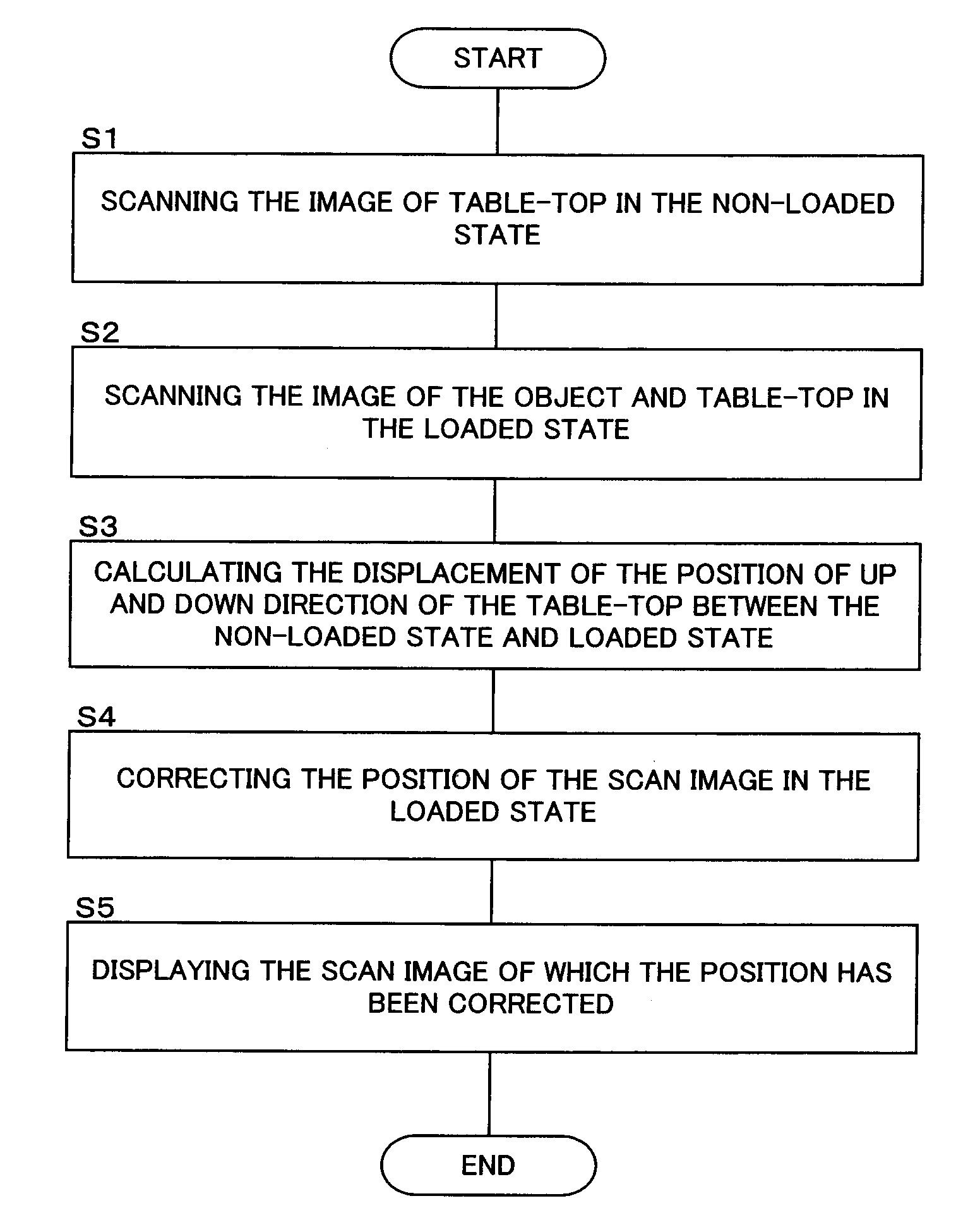
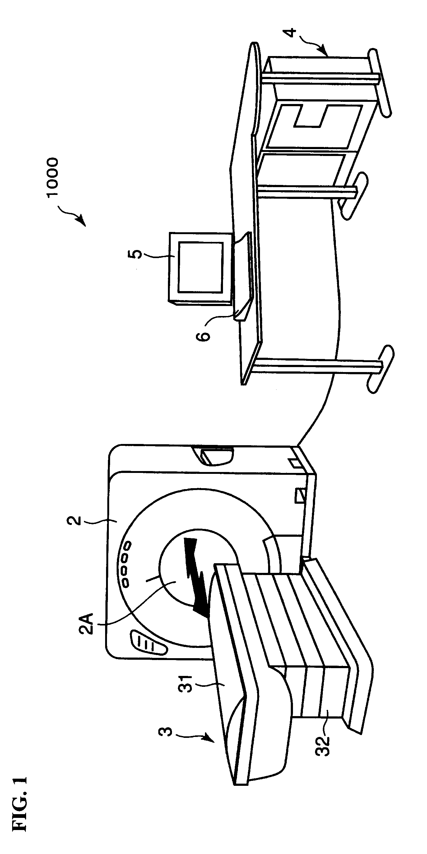
According to the above mentioned first type of usage, markers 31 (i) are provided at the location for determining the displacement of the patient table 31 (reference position) in vertical direction to indicate the reference position. Instead of providing such markers 31 (i), distinctive positions of the patient table 31 may be set to reference positions to determine the displacement of the patient table 31.

For example, the edge of the patient table 31 near the gantry 2 may be the reference position. In that case, for example, the patient table 31 in the non-loaded state is assumed to be horizontal (in other words, the y-coordinate value of the patient table 31 at any location is assumed to be equal to the y-coordinate value of said edge).

Furthermore, for a tomographic image at any slice location in the loaded state, the y-coordinate value of the image of the patient table 31 in the tomographic image is determined to calculate the displacement of the y-coordinate value and the y-coor...

modified embodiment 2

In the above mentioned first type of usage, the markers 31 (i) are provided at the reference position that determines the displacement of the patient table 31 in vertical direction to determine the displacement of the image position of the patient table 31 in the non-loaded state and the position of the patient table 31 in the loaded state for each reference position, and correct the vertical position of the image of the object P at this reference position.

embodiment 2

This modified embodiment 2 describes a construction that corrects the position of the image of the object P at locations other than prescribed reference position.

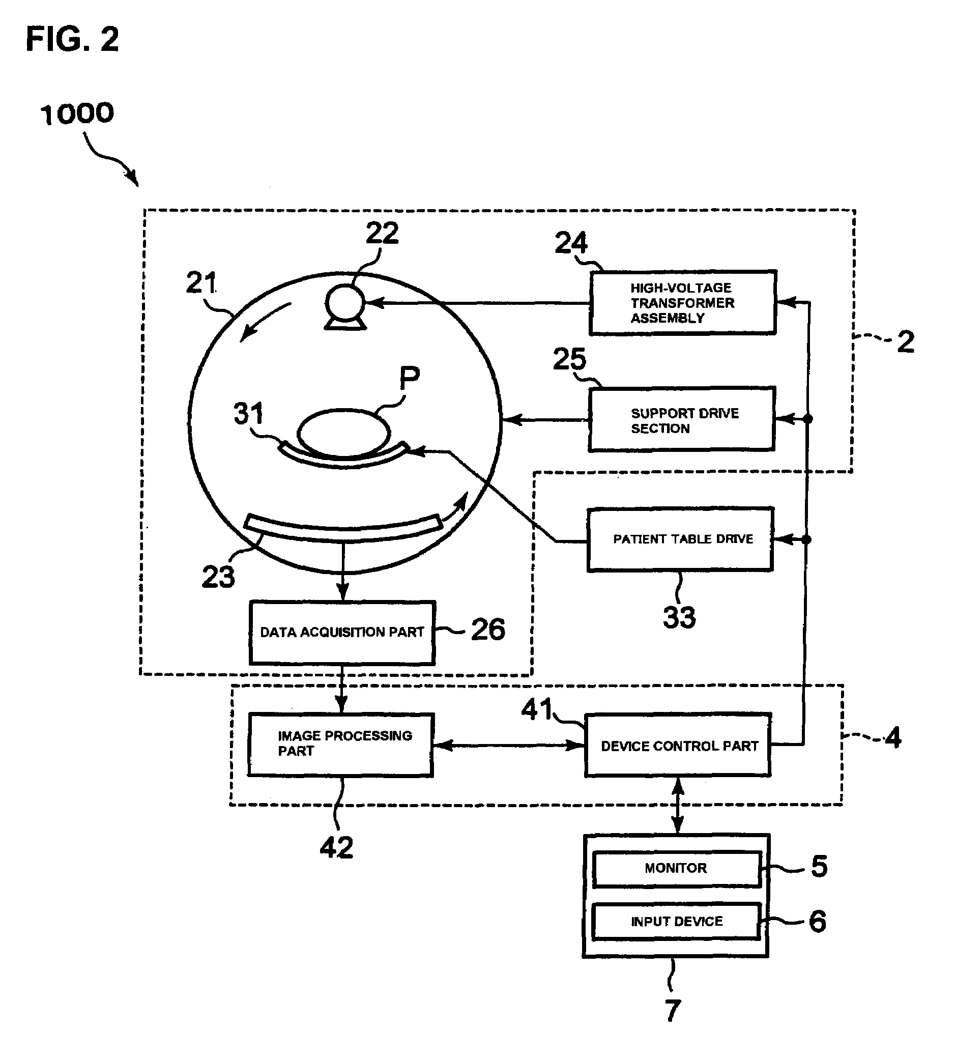
In the modified embodiment 2, the displacement calculation part 45, similar to the first type of usage, firstly acquires the location of the tomographic image g (i) of the patient table 31y0 (i) acquired in the non-loaded state and the location of the tomographic image G (i) of the patient table 31y (i) acquired in the loaded state at the reference position indicated by each marker 31 (i). Then, the displacement calculation part 45 calculates the difference of these positions between y0 (i) and y (i) to determine the displacement Δy (i) in up and down direction (y-direction) at said reference position.

Furthermore, the displacement calculation part 45 calculates the displacement Δy (ζ) at any position between the two reference positions (z-coordinate value=ζ) based on the displacement Δy (i), Δy (i+1), which are calculated f...


PUM


Abstract

Obtain a tomographic image of a patient table in advance in a state in which the object is not placed on the patient table. Obtain a tomographic image of the patient table with the object placed on the patient table. This tomographic image consists of an image of a patient table. The displacement calculation part determines the vertical displacement of images of the patient table in a non-loaded state and the tomographic image of the patient table in a loaded state. Meanwhile, markers are placed on the side of the patient table to indicate the displacement detecting position (reference position). The corrected image-forming part corrects the vertical positions of image data of the tomographic image in the loaded state based on the calculated displacement.

Description

BACKGROUND OF THE INVENTION1. Field of the InventionThe present invention relates to a medical image diagnosis apparatus and the control method thereof that forms a medical image of an object. In particular, it relates to techniques that correct displacement of an image caused by bending of the patient table (patient table deflection) on which an object is placed.2. Description of the Related ArtConventionally, medical image diagnosis apparatuses such as the X-ray CT apparatus and nuclear medical diagnosis apparatus (PET, SPECT, etc.) have been widely used (refer to Japanese Unexamined Patent Application Publication No. 2004-180846 as an example). In recent years, diagnostic systems that combine an X-ray CT apparatus with a nuclear medical diagnosis apparatus, such as a PET-CT, are also in practical use (refer to Japanese Unexamined Patent Application Publication No. 2005-291814 as an example).An example of construction of a general medical image diagnosis apparatus (X-ray CT appara...

Claims


Application Information

Patent Timeline
Patent Type & Authority Patents(United States)
IPC IPC(8): G06K9/00
CPCG06T7/0012A61B6/5276A61B6/032A61B6/0457A61B6/0492A61B6/5205A61N5/1049A61B6/0407A61B6/027A61N2005/1061A61B6/0487
Inventor NABATAME, TAKEOSASAKI, TOMIYA
Owner TOSHIBA MEDICAL SYST CORP
Why Eureka
Try Eureka