Method for design and production of a custom-fit prosthesis

a prosthesis and custom-fit technology, applied in the direction of impression caps, programme control, instruments, etc., can solve the problems of insufficient autogenous material to use for repair, less than desirable appearance, and difficulty in considering the reconstruction of a bilateral defect, and the symmetry between the right and left sides of the head

Active Publication Date: 2011-12-27
3D SYST INC
View PDF41 Cites 238 Cited by
  • Summary
  • Abstract
  • Description
  • Claims
  • Application Information

AI Technical Summary

Problems solved by technology

Many times a repair and recontouring of a defect of this type will involve either autogenous (body tissue) or alloplastic (man-made) materials, but in many cases of large defects there is not enough autogenous material to use for repair.
The current method exposes the patient to longer surgery and often leaves a less than desirable appearance, especially with large defects.
Issues of symmetry between the right and left sides of the head and reconstruction of a bilateral defect are difficult to consider when forming the implant during surgery.

Method used


Image

  • Method for design and production of a custom-fit prosthesis
  • Method for design and production of a custom-fit prosthesis
  • Method for design and production of a custom-fit prosthesis

Examples


first embodiment

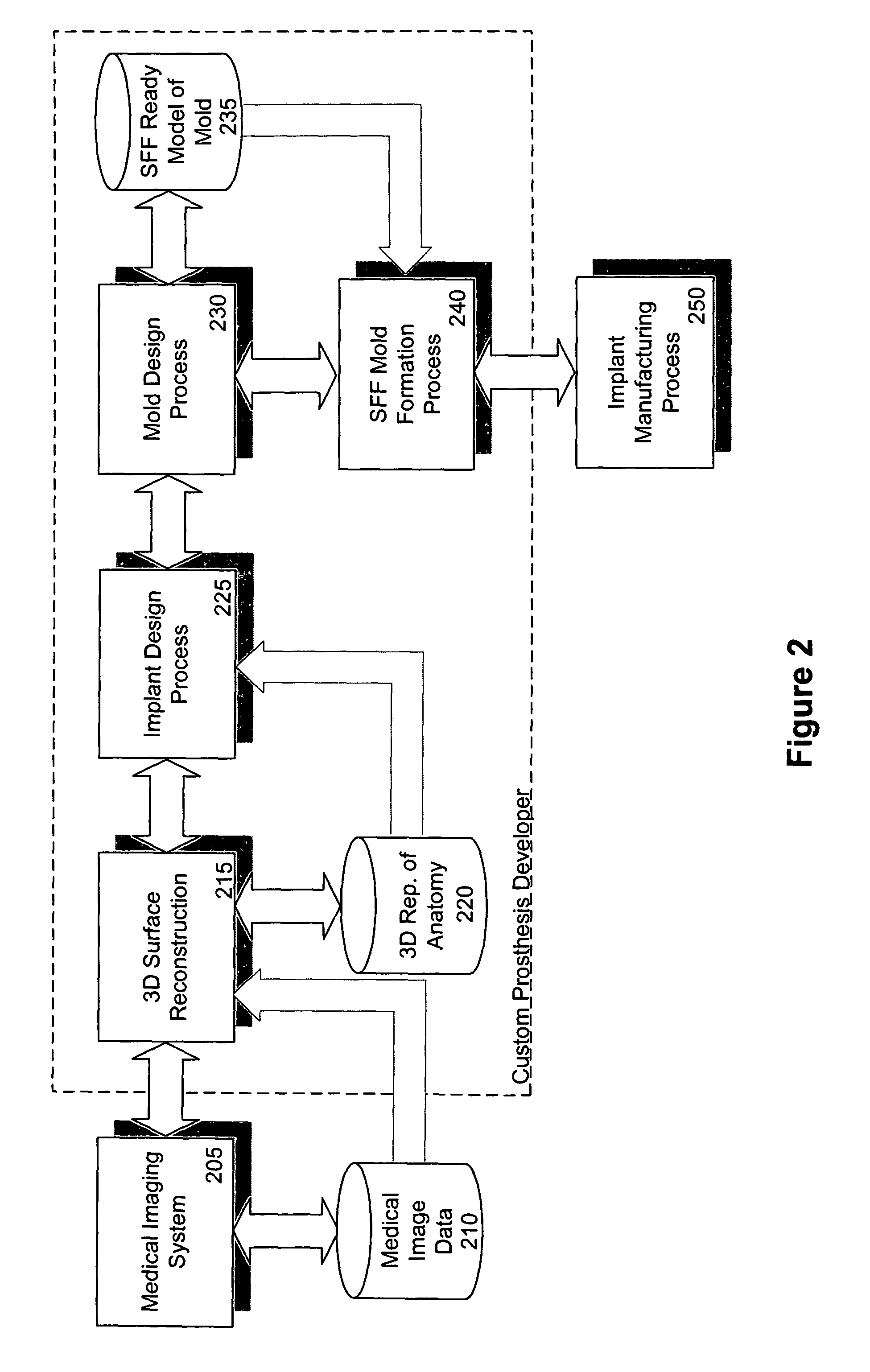
[0060]FIG. 2 is a block diagram that conceptually illustrates a custom prosthesis development system according to the present invention in which the final mold from which the implant may be directly manufactured or data files representative thereof may be delivered to an implant manufacturer. Medical image data 210 is collected via a CT scan or some other medical imaging modality that allows for the visualization of a defect to be corrected. A medical imaging system 205 may be used to visualize the medical image data 210 on the computer to see the defect in three dimensions. Using the medical image data 210 or the medical imaging system 205 representation, a three-dimensional virtual surface reconstruction 215 can be made. Data pertaining to a three-dimensional representation of the patient's anatomy 220 may also be used and / or created in the three-dimensional surface reconstruction 215. The three-dimensional representation of the patient's anatomy 220 and the three-dimensional surf...

third embodiment

[0067]FIG. 4 is a block diagram that conceptually illustrates a custom prosthesis development system according to the present invention in which the implant or data files representative thereof may be delivered. Medical image data 410 is collected via a CT scan or some other medical imaging modality that allows for the visualization of a defect to be corrected. A medical imaging system 405 may be used to visualize the medical image data 410 on the computer to see the defect in three dimensions. Using the medical image data 410 or the medical imaging system 405 representation sent to a custom prosthesis developer, a three-dimensional virtual surface reconstruction 415 can be made. Data pertaining to a three-dimensional representation of the patient's anatomy 420 may also be used and / or created in the three-dimensional surface reconstruction 415. The three-dimensional representation of the patient's anatomy 420 and the three-dimensional surface reconstruction 415 are then imported int...


PUM

PropertyMeasurementUnit
defectsaaaaaaaaaa
timeaaaaaaaaaa
symmetryaaaaaaaaaa

Abstract

Systems and methods are provided for designing and producing a custom-fit prosthesis. According to one embodiment, a mold is produced from which a custom-fit implant may be directly or indirectly manufactured. Medical image data representing surrounding portions of a patient's anatomy to be repaired by surgical implantation of the custom-fit implant are received. Then, three-dimensional surface reconstruction is performed based on the medical image data. Next, the custom-fit implant is designed based on the three-dimensional surface reconstruction and a positive or negative representation of a two-part mold is created with a void in the shape of the custom-fit implant by subtracting a representation of the custom-fit implant from a representation of a mold. Finally, the two-part mold is output from which the custom-fit implant may be directly manufactured; or an implant is directly output. Alternatively, an intermediate mold is created from which a two-part mold may be directly manufactured.

Description

[0001]This application is a continuation in part of U.S. application Ser. No. 10 / 676,661, filed Sep. 30, 2003, entitled “Method for Design and Production of a Custom-Fit Prosthesis;” and claims the benefit of U.S. Provisional Application No. 60 / 414,585, filed Sep. 30, 2002, entitled “Method for Design and Production of a Custom-Fit Cranioplasty Prosthesis;” and U.S. Provisional Application No. 60 / 437,489, filed Dec. 31, 2002, entitled “Method for Design and Production of a Custom-Fit Cranioplasty Prosthesis;” each of which is hereby incorporated by reference in its entirety.COPYRIGHT NOTICE[0002]Contained herein is material that is subject to copyright protection. The copyright owner has no objection to the facsimile reproduction of the patent disclosure by any person as it appears in the Patent and Trademark Office patent files or records, but otherwise reserves all rights to the copyright whatsoever. Copyright© 2002-2004 Medical Modeling, LLC.BACKGROUND[0003]1. Field[0004]Embodime...

Claims


Application Information

Patent Timeline
Patent Type & Authority Patents(United States)
IPC IPC(8): B29C33/40G06F19/00B29C39/08A61C9/00A61C13/00B29C35/08B29C41/02
CPCA61C13/0004G05B19/4097A61C9/004G05B2219/45168G05B2219/45204G05B2219/49013G06F19/3437A61C9/0046G16H50/50A61F2/2875A61F2/30942A61F2002/30948A61F2002/30957A61F2310/00353B33Y80/00A61B34/10G16H20/40
Inventor CHRISTENSEN, ANDREW M.
Owner 3D SYST INC
Why Eureka
Try Eureka