Suspension control apparatus

a control apparatus and suspension technology, applied in the direction of process and machine control, cycle equipment, instruments, etc., can solve the problems of difficult to use this control apparatus in a real environment, the required force cannot always be generated, and the simple practical use of the control apparatus is difficult to achieve. , to achieve the effect of excellent vibration control and reduced vehicle vibration

Inactive Publication Date: 2011-12-27
HITACHI LTD +1
View PDF0 Cites 2 Cited by
  • Summary
  • Abstract
  • Description
  • Claims
  • Application Information

AI Technical Summary

Benefits of technology

[0005]The present invention has been contrived in consideration of the above-mentioned circumstance, and an object thereof is to provide a suspension control apparatus capable of performing an excellent vibration control by taking into consideration nonlinearity and a time-lag element of a control damper when designing a model thereof.

Problems solved by technology

However, the suspension control apparatus disclosed by Fukao et al. employs a first-order linear model, which is too simple for practical use, as the model of the actuator (control damper) used in the control apparatus.
Therefore, it is difficult to use this control apparatus in a real environment as it is.
In a suspension control apparatus, since an actuator (control damper) used therein generally has strong nonlinearity and a time-lag element, a required force cannot be always generated at a required time, and a difference (error) between required and generated forces may occur.
Although there has been a demand for preventing this situation from occurring, conventional arts have been unable to take any measures for it.

Method used


Image

  • Suspension control apparatus
  • Suspension control apparatus
  • Suspension control apparatus

Examples


Embodiment Construction

[0018]Hereinafter, a suspension control apparatus of an embodiment of the present invention will be described with reference to the accompanying drawings.

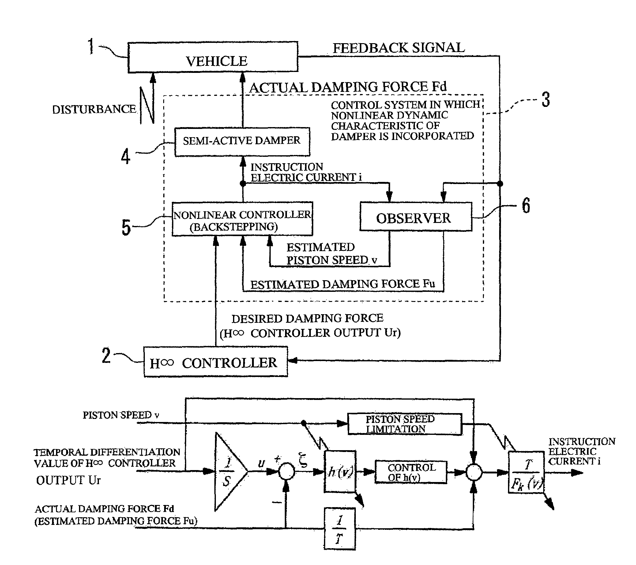
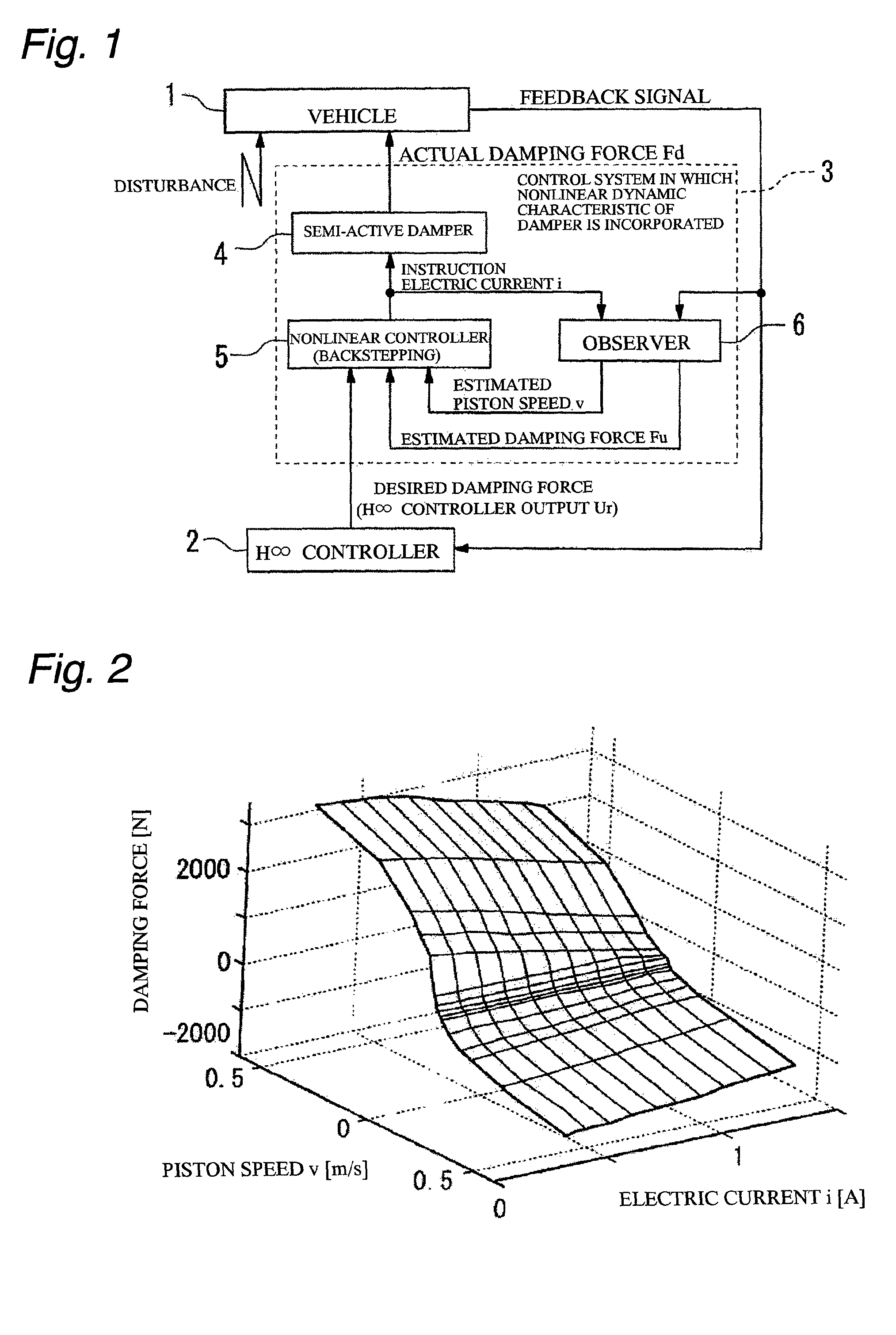
[0019]FIG. 1 is a block diagram schematically illustrating a suspension control apparatus of an embodiment of the present invention. Referring to FIG. 1, the suspension control apparatus of the present embodiment of the present invention comprises an H∞ controller 2 operable to calculate a desired damping force (desired control force) based on a vibration signal (feedback signal) indicating a vibration state of a vehicle 1, and a control system 3 operable to provide an actual damping force Fd to the vehicle 1 by receiving an input of the desired damping force (an output ur of the H∞ controller) provided from the H∞ controller 2. The vibration signal of the vehicle 1 is output from movement detecting means disposed at the vehicle 1 and operable to detect a movement (for example, an acceleration, a speed, and a displacement) of a ver...


PUM


Abstract

The present invention provides a suspension control apparatus capable of an excellent vibration control by a model thereof designed to incorporate nonlinearity and a time-lag element of a control damper. The present invention employs the backstepping method which is one of nonlinear control methods, and is designed so as to incorporate the nonlinearity of a damper 4. In addition, a nonlinear controller 5 uses a damping force Fu obtained by expressing the dynamics of a damping force characteristic variable portion [damping force Fu(v, i)] by a first-order lag system, so as to compensate the dynamics of the damper 4, whereby a control system is formed so as to incorporate the time-lag element of the control damper. As a result, it is possible to reduce time lag, and to practically adjust a control force according to the characteristics of the control damper.

Description

BACKGROUND OF THE INVENTION[0001]The present invention relates to a suspension control apparatus operable to control vibration of a vehicle such as automobile with use of a control damper.[0002]As an example of conventional suspension control apparatus, there is known a suspension control apparatus in which a model of an actuator used in the control apparatus is taken into consideration (non-patent literature 1: “Control Design Method of Semi-Active Suspensions with Actuators” presented by Takanori Fukao, Takafumi Suzuki and Koichi Osuka at the Society of Instrument and Control Engineers Control Division Fifth Conference held on May 25-27, 2005, which is hereby incorporated by reference herein).SUMMARY OF THE INVENTION[0003]However, the suspension control apparatus disclosed by Fukao et al. employs a first-order linear model, which is too simple for practical use, as the model of the actuator (control damper) used in the control apparatus. Therefore, it is difficult to use this cont...

Claims


Application Information

Patent Timeline
Patent Type & Authority Patents(United States)
IPC IPC(8): G05D3/12
CPCB60G17/08B60G2400/102B60G2400/20B60G2400/252B60G2500/104B60G2600/02B60G2600/184B60G2600/187B60G2600/1872B60G17/00B60G17/015
Inventor ITAGAKI, NORIAKIICHIMARU, NOBUYUKIKOBAYASHI, TAKAHIDEGANKAI, TATSUYAFUKAO, TAKANORI
Owner HITACHI LTD
Why Eureka
Try Eureka