
Heat pump defrost system

a heat pump and defrosting technology, applied in the direction of defrosting, cooling devices, instruments, etc., can solve the problems of less efficient heat sources, and often times less efficient back-up heat sources, and achieve the effect of efficient defrosting an outdoor coil

Inactive Publication Date: 2012-01-10
EKERN MARK
View PDF22 Cites 16 Cited by
  • Summary
  • Abstract
  • Description
  • Claims
  • Application Information

AI Technical Summary

Benefits of technology

[0013]An object is to provide a heat pump defrost system for efficiently defrosting an outdoor coil while simultaneously operating the heat pump in a normal heating manner.

Problems solved by technology

The back-up heat source, however, is often times less efficient than the heat pump.
Thus, the heat pump is operating at a high efficiency to defrost the outdoor coils and the primary area of interest, which is the interior space of the home, is being heated with a less efficient heat source, such as an electric heater.
This can add to costs associated with heating a home, as well as an overall uncomfortable feeling of the house becoming slightly cooler while waiting for the electric heat source to take over and heat the house while the heat pump is in the defrosting cycle.

Method used


Image

  • Heat pump defrost system
  • Heat pump defrost system
  • Heat pump defrost system

Examples


Embodiment Construction

A. Overview

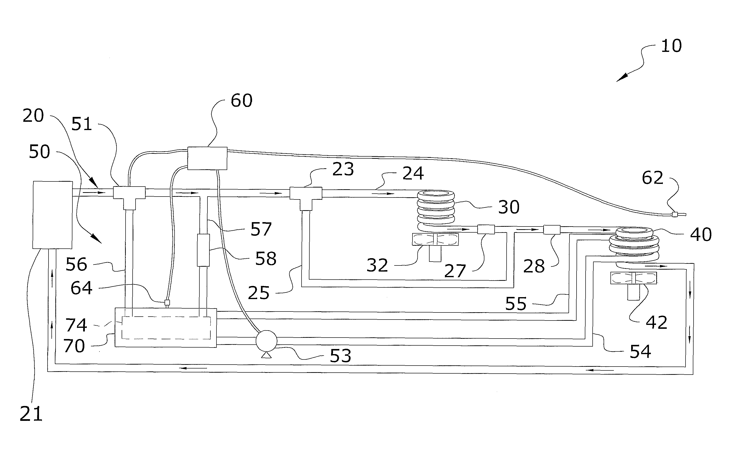
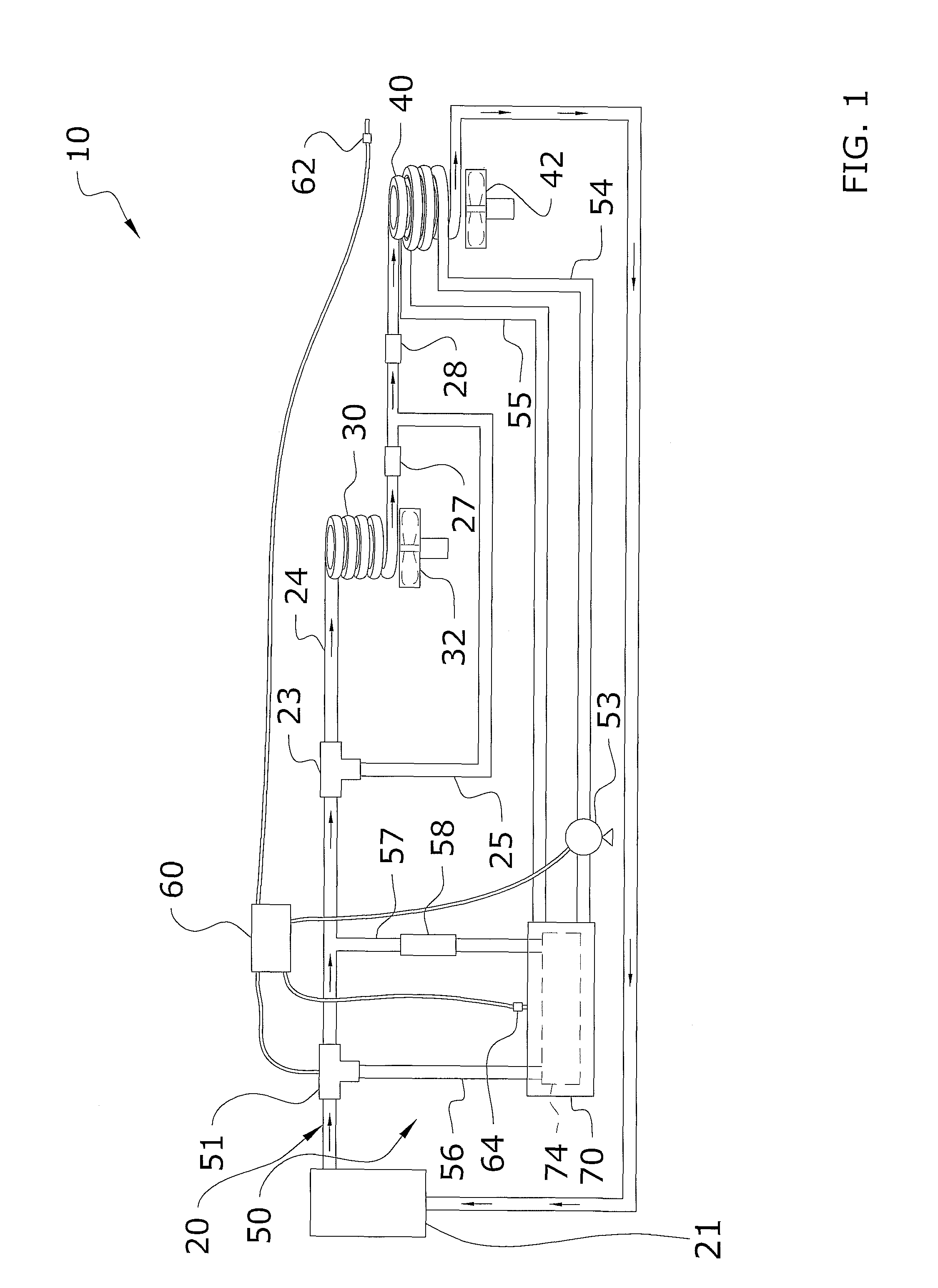
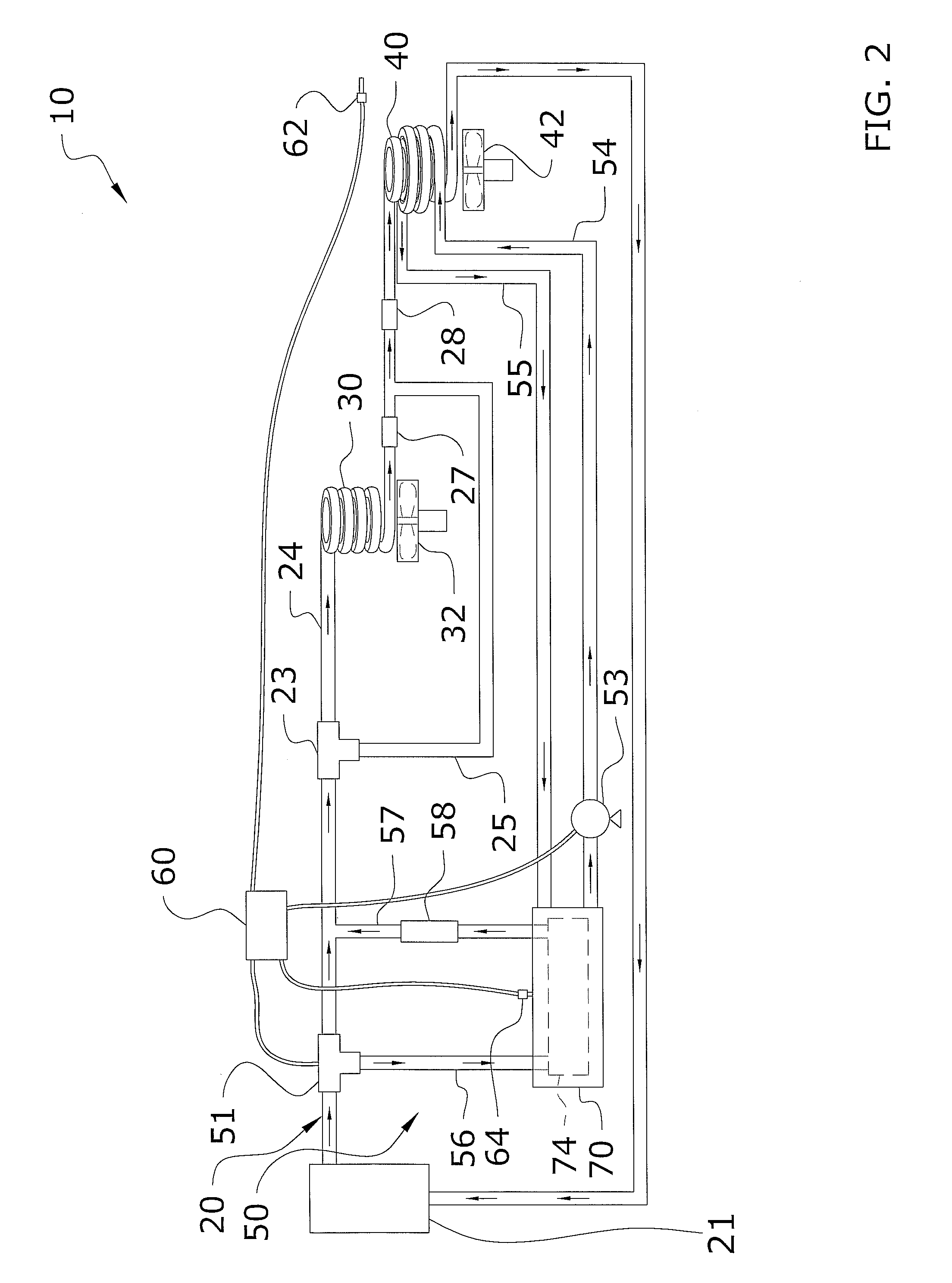
[0024]Turning now descriptively to the drawings, in which similar reference characters denote similar elements throughout the several views, FIGS. 1 through 5 illustrate a heat pump defrost system 10, which comprises a primary flow circuit 20 including an indoor heat exchanger 30, an outdoor heat exchanger 40, a compressor 21 connected thereto and a reverse valve 23 for toggling a direction of refrigerant flow therethrough, and an auxiliary flow circuit 50 for deicing the outdoor heat exchanger 40. The auxiliary flow circuit 50 includes a valve 51 for connecting the auxiliary flow circuit 50 to the primary flow circuit 20, a heat sink 70 in line with the auxiliary flow circuit 50, wherein the heat sink 70 stores defrost fluid within the auxiliary flow circuit 50, at least one thermostat 62 to read an outdoor ambient temperature and a control unit 60 for operatively engaging the valve 51 to direct hot gas within the auxiliary flow circuit 50 and the heat pump 10 according ...


PUM


Abstract

A heat pump defrost system for efficiently defrosting an outdoor coil while simultaneously operating the heat pump in a normal heating manner. The heat pump defrost system generally includes a primary flow circuit including an indoor heat exchanger, an outdoor heat exchanger, a compressor connected thereto and a reverse valve for toggling a direction of refrigerant flow therethrough, and an auxiliary flow circuit for deicing the outdoor heat exchanger. The auxiliary flow circuit includes a valve for connecting the auxiliary flow circuit to the primary flow circuit, a heat sink in line with the auxiliary flow circuit, wherein the heat sink stores defrost fluid within the auxiliary flow circuit, at least one thermostat to read an outdoor ambient temperature and a control unit for operatively engaging the valve to direct the hot gas from the compressor of the primary circuit within the auxiliary flow circuit and the heat pump according to the outdoor ambient temperature for deicing the outdoor heat exchanger.

Description

CROSS REFERENCE TO RELATED APPLICATIONS[0001]Not applicable to this application.STATEMENT REGARDING FEDERALLY SPONSORED RESEARCH OR DEVELOPMENT[0002]Not applicable to this application.BACKGROUND OF THE INVENTION[0003]1. Field of the Invention[0004]The present invention relates generally to air source heat pumps and more specifically it relates to a heat pump defrost system for efficiently defrosting an outdoor coil while simultaneously operating the heat pump in a normal heating manner.[0005]2. Description of the Related Art[0006]Any discussion of the related art throughout the specification should in no way be considered as an admission that such related art is widely known or forms part of common general knowledge in the field.[0007]Air source heat pumps are commonly utilized for heating and cooling interior spaces of homes because of their high efficiency that lead to cost savings over time. The heat pumps transfer energy in the form of heat from a cooler location to a warmer loc...

Claims


Application Information

Patent Timeline
Patent Type & Authority Patents(United States)
IPC IPC(8): F25D21/00
CPCF25D21/00F25B13/00F25B29/003F25B47/02F25D21/025F25B2700/11F25B2700/2106
Inventor EKERN, MARK
Owner EKERN MARK
Learn More