Method and apparatus for facilitating navigation of an implant

a technology for implant navigation and navigation, applied in the field of surgical implants, can solve the problems of increasing the possibility of pathway divergence and/or reducing the risk of causing damage to neural structures or bony obstructions, and reducing the risk of causing damage to neural and vascular structures. , the effect of reducing x-ray exposure and fewer complications

Active Publication Date: 2012-01-10
NUVASIVE
View PDF23 Cites 16 Cited by
  • Summary
  • Abstract
  • Description
  • Claims
  • Application Information

AI Technical Summary

Benefits of technology

[0018]It therefore an objective of the instant invention to provide a system that minimizes soft tissue damage and provides less post-operative pain.
[0019]Yet another objective of the present invention is to provide a targeting system that permits percutaneous positioning of a biocompatible device at multiple vertebral levels of greater than three.
[0020]Another objective of the present invention is to provide a targeting system that can percutaneously treat scoliosis patients.
[0021]Still a further objective of the invention is to teach a targeting system which allows for shorter surgery, decreased x-ray exposure, and fewer complications for the patient.
[0022]Yet another objective of the instant invention is to provide a targeting system that is simple to operate to reduce the training the surgeon must undergo for operation of peripheral systems.

Problems solved by technology

Although there are numerous patents directed to systems and methods for insertion of a stabilizing implant at a selected area of an anatomy, the prior art nevertheless fails to teach a targeting system for the insertion of an implant using minimally invasive techniques having a decreased risk of causing damage to neural structures or bony obstructions using minimal, if any, radiation exposure to the patient and / or surgeon.
This increases the possibility of pathway divergence and / or damage to neural and vascular structures.
Moreover, none of the aforementioned references provide audible and / or tactile feedback to the surgeon that indicates the target area has been reached.

Method used


Image

  • Method and apparatus for facilitating navigation of an implant
  • Method and apparatus for facilitating navigation of an implant
  • Method and apparatus for facilitating navigation of an implant

Examples


Embodiment Construction

[0035]Detailed embodiments of the instant invention are disclosed herein, however, it is to be understood that the disclosed embodiments are merely exemplary of the invention, which may be embodied in various forms. Therefore, specific functional and structural details disclosed herein are not to be interpreted as limiting, but merely as a basis for the claims and as a representation basis for teaching one skilled in the art to variously employ the present invention in virtually any appropriately detailed structure.

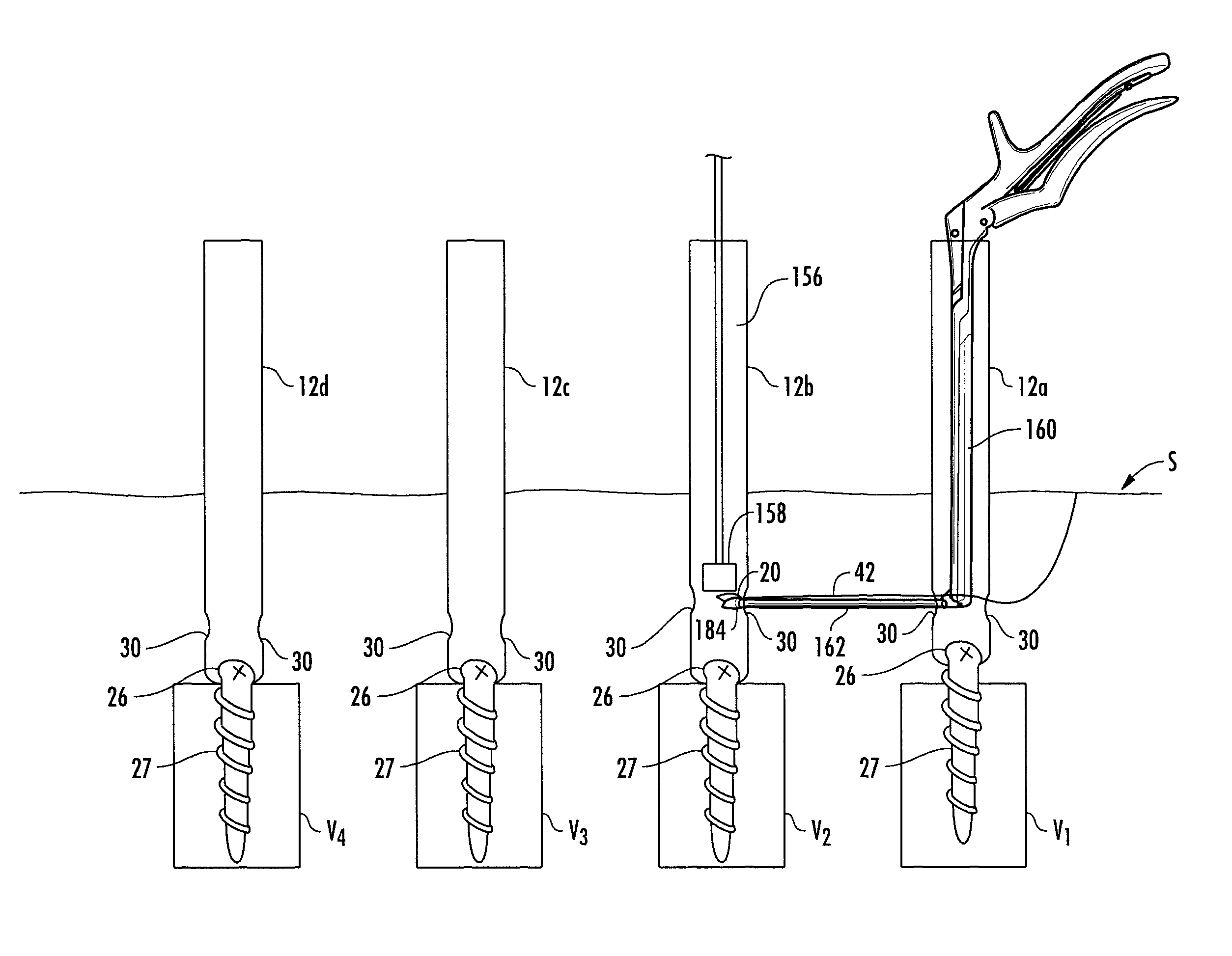
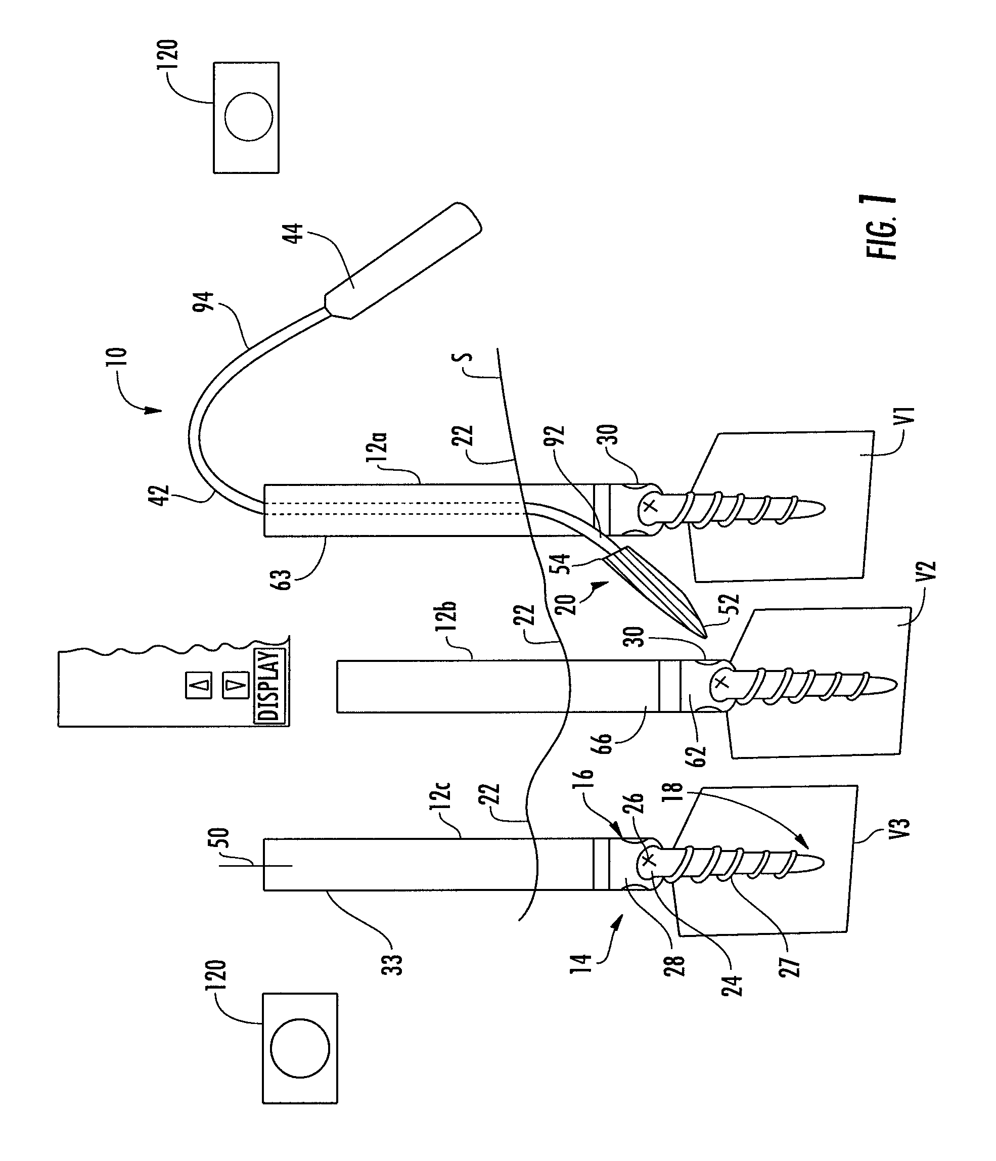
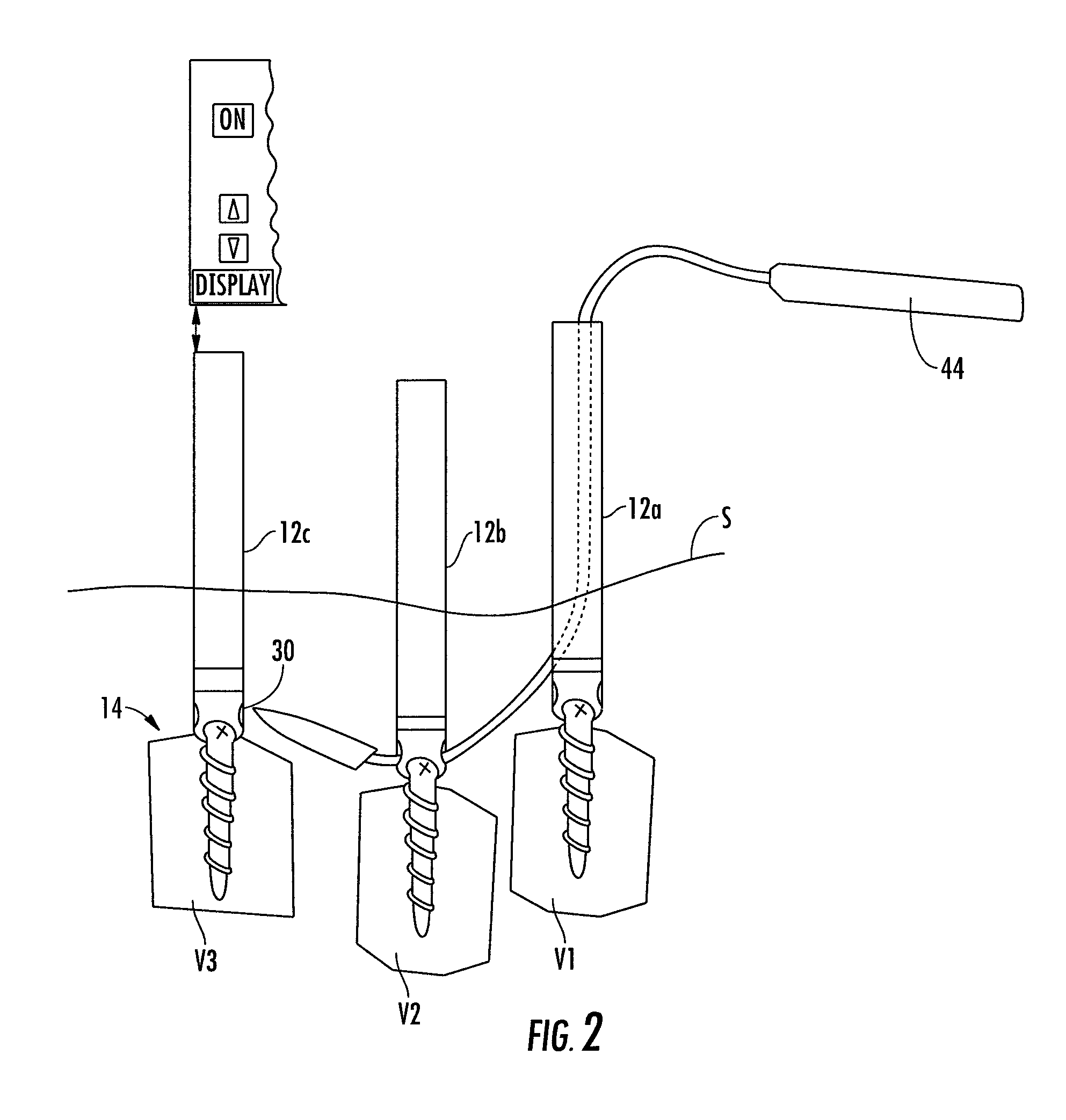
[0036]Referring now to FIGS. 1-8 which illustrate the targeting system 10 of the present invention suitable for facilitating navigation to a target area, wherein like elements are numbered consistently throughout. FIG. 1 shows a plurality of anchoring members 14 (also referred to as fastening means). The anchoring members are depicted here as multi-axial pedicle screws, each removably attached to an extender 12a, 12b, and 12c. These screws have a proximal end 16 and a dis...


PUM


Abstract

The present invention describes a targeting system suitable for guiding a biocompatible device to a target area within the body (in vivo) and method of using the same. The system includes a targeting member that is attached to the biocompatible device and may optionally include a steering material. The system includes a passer element located at the distal end of a wand. The wand includes a trigger like member adjacent a hand grip. Actuation of the trigger like member will result in a pivotal movement of the passer element that positions the targeting member such that the connected biocompatible device is positionable relative to the target area.

Description

CROSS REFERENCE TO RELATED APPLICATIONS[0001]This application is a continuation-in-part of U.S. application Ser. No. 12 / 157,397, filed on Jun. 10, 2008, entitled, “Magnetic Targeting System For Facilitating Navigation”, which in turn is a continuation-in-part of U.S. application Ser. No. 11 / 462,592, filed on Aug. 4, 2006, entitled, “Magnetic Targeting System and Method of Using The Same,” which are hereby expressly incorporated by reference.FIELD OF THE INVENTION[0002]The invention generally relates to surgical implants; particularly to a system and method for stabilization of adjacent bony structures; most particularly to a system to help navigate an interconnecting means between multiple bony stabilization devices.BACKGROUND OF THE INVENTION[0003]It is widely held that healing and / or structural correction is greatly facilitated when a bone is stabilized in the proper position. Various devices for stabilization of bone are well known and routinely practiced in the medical arts. For...

Claims


Application Information

Patent Timeline
Patent Type & Authority Patents(United States)
IPC IPC(8): A61B17/70
CPCA61B17/7002A61B17/7083A61B19/22A61B17/7085A61B2017/003A61B2019/2253A61B34/73A61B34/70
Inventor GEIST, WYATT DRAKEWALSH, CHRISTOPHER
Owner NUVASIVE
Why Eureka
Try Eureka