Module and method for producing a module

a technology of modules and manufacturing methods, applied in the direction of electrical apparatus casings/cabinets/drawers, instruments, semiconductor/solid-state device details, etc., can solve the problems of low manufacturing tolerance, comparatively complex manufacturing process, and low manufacturing efficiency of covers, so as to avoid the problem of tolerance between multiple components and reduce the manufacturing effort of modules , the effect of cost-effective production of modules

Active Publication Date: 2012-01-10
ROBERT BOSCH GMBH
View PDF5 Cites 0 Cited by
  • Summary
  • Abstract
  • Description
  • Claims
  • Application Information

AI Technical Summary

Benefits of technology

[0004]Example embodiments of a module and a method for producing a module have the advantage in relation to conventional arrangements that comparatively high-quality EMC shielding of the at least one component is achieved with significantly less manufacturing effort of the module than in conventional arrangements. More cost-effective production of the module is thus made possible. Situating the at least one component between the carrier element and the connection element, which is provided in particular in the area of the at least one component lying at a constant electrical potential, causes electromagnetic shielding of the component in the direction of the connection element and also in the direction of the carrier element, because the carrier element preferably includes a circuit board or card. It is particularly advantageous that no additional cover of the module housing and / or the component must be produced, mounted, and / or electrically contacted for shielding the component, because the connection element preferably has a contact to ground in any case, which is only connected by suitable structuring of the connection element to the connection element area of the component. The electrically conductive connection element, which is produced and structured in comparatively simple and well controllable stamping, bending, and / or embossing processes, concurrently functions as a plurality of contact decks for electrical contacting of the at least one component, as a carrier for the mechanically stable fixing of the component, and for EMC shielding of the component. Therefore, additional components for contacting, fixing, and / or shielding the component and the corresponding work steps for mounting, producing, and / or contacting them are advantageously not necessary. Furthermore, because of the integral design of the connection element, tolerance problems between multiple components are avoided and the production process is thus significantly simplified.
[0005]According to example embodiments, the connection element has a closed and / or conductive protective face in an overlap area with the at least one component parallel to the surface normal of the carrier element. The EMC shielding of the at least one component is thus advantageously increased.
[0007]According to example embodiments, the connection element has contact pins, which extend parallel to the surface normal from the contacting plane up to the carrier element, and / or the module housing includes a further module housing cover, which is situated between the at least one component and the carrier element. Contact pins of this type advantageously allow simple contacting of the connection element by the carrier element, which preferably has a plurality of printed conductors in the area of the contact pin. The module housing, preferably a mold housing or pre-mold housing, particularly advantageously has the further module housing cover, which produces an isolated atmosphere in the module housing, preferably for protecting the at least one component.
[0011]According to example embodiments of the present invention, a composite is made of the module housing, the connection element, and the at least one component for use in a module. The composite advantageously allows the implementation of an EMC-shielded module in a simple manner solely by mounting and / or contacting the composite on a circuit board and / or a card.
[0013]According to example embodiments, the module housing cover is electrically conductive, the module housing cover includes an electrically conductive shielding element, and / or the module housing cover is latched to the module housing. A nonconductive module housing cover is advantageously connected to an electrically conductive shielding element, which has a mechanical contact to the electrically conductive spring device, so that EMC shielding is implemented at least partially in the area of the module housing cover. Latching of the module housing cover to the module housing is preferably provided such that the mounting of the module housing cover is performed particularly advantageously by simple insertion thereof into the module housing.
[0014]According to example embodiments, the electrically conductive spring device, the conductive shielding element, and / or the module housing cover are connected to one another using conductive adhesive, a press contact, and / or a laser welding contact. A cost-effective and simple production of the EMC-shielded module is thus advantageously made possible, in particular the module housing cover and the electrically conductive spring device and / or the conductive shielding element, the module housing cover, and the electrically conductive spring device being connected integrally, so that simple mounting in the module housing may be implemented solely by pressing this one part into the module housing.

Problems solved by technology

It has the disadvantage that the cover must be manufactured in a comparatively complex and time-consuming production and mounting method having low manufacturing tolerance, integrated in the housing main body, and subsequently additionally electrically contacted with the main body via a terminal pin.

Method used


Image

  • Module and method for producing a module
  • Module and method for producing a module
  • Module and method for producing a module

Examples


Embodiment Construction

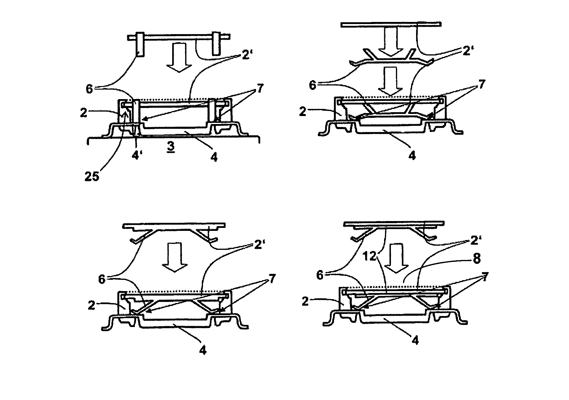
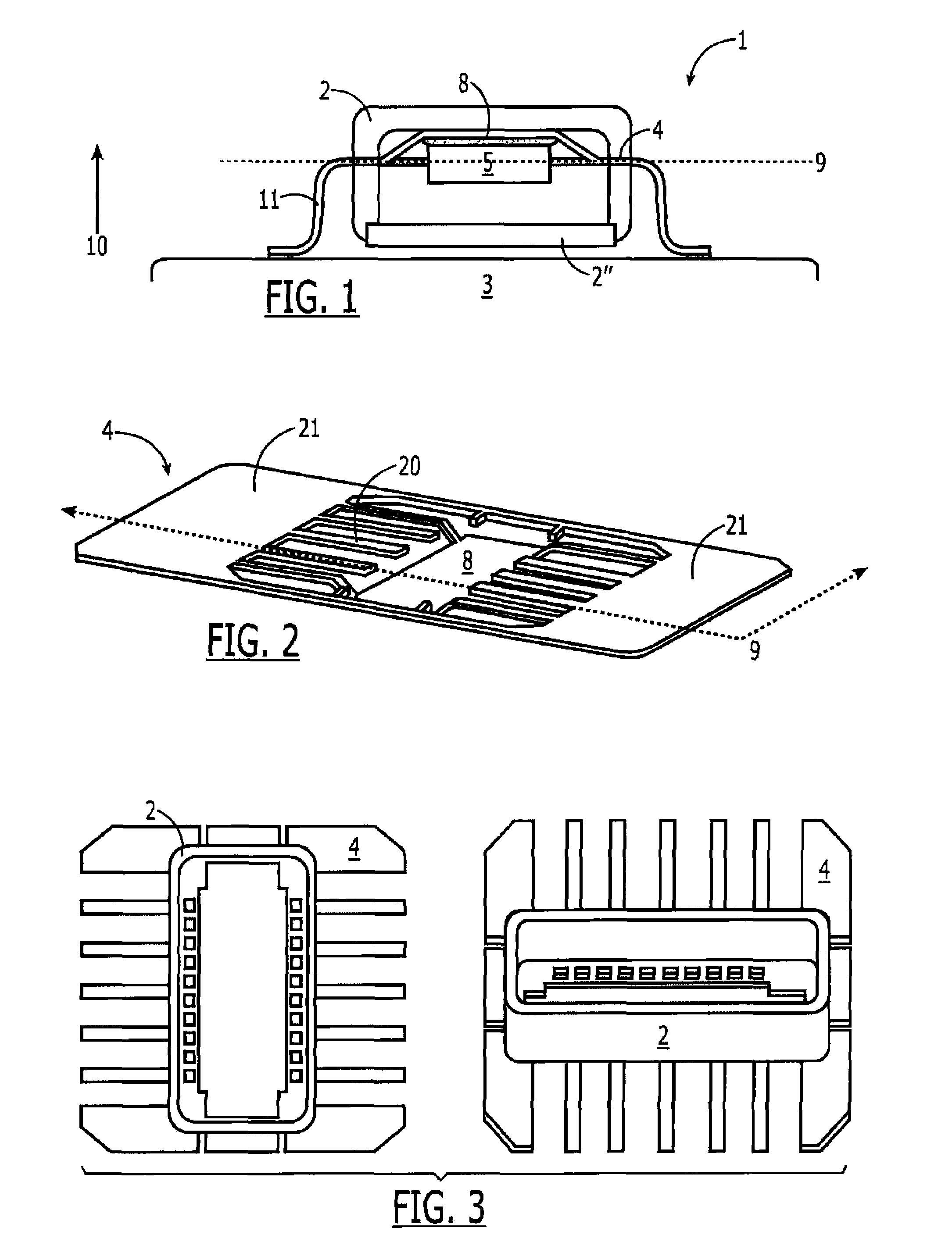
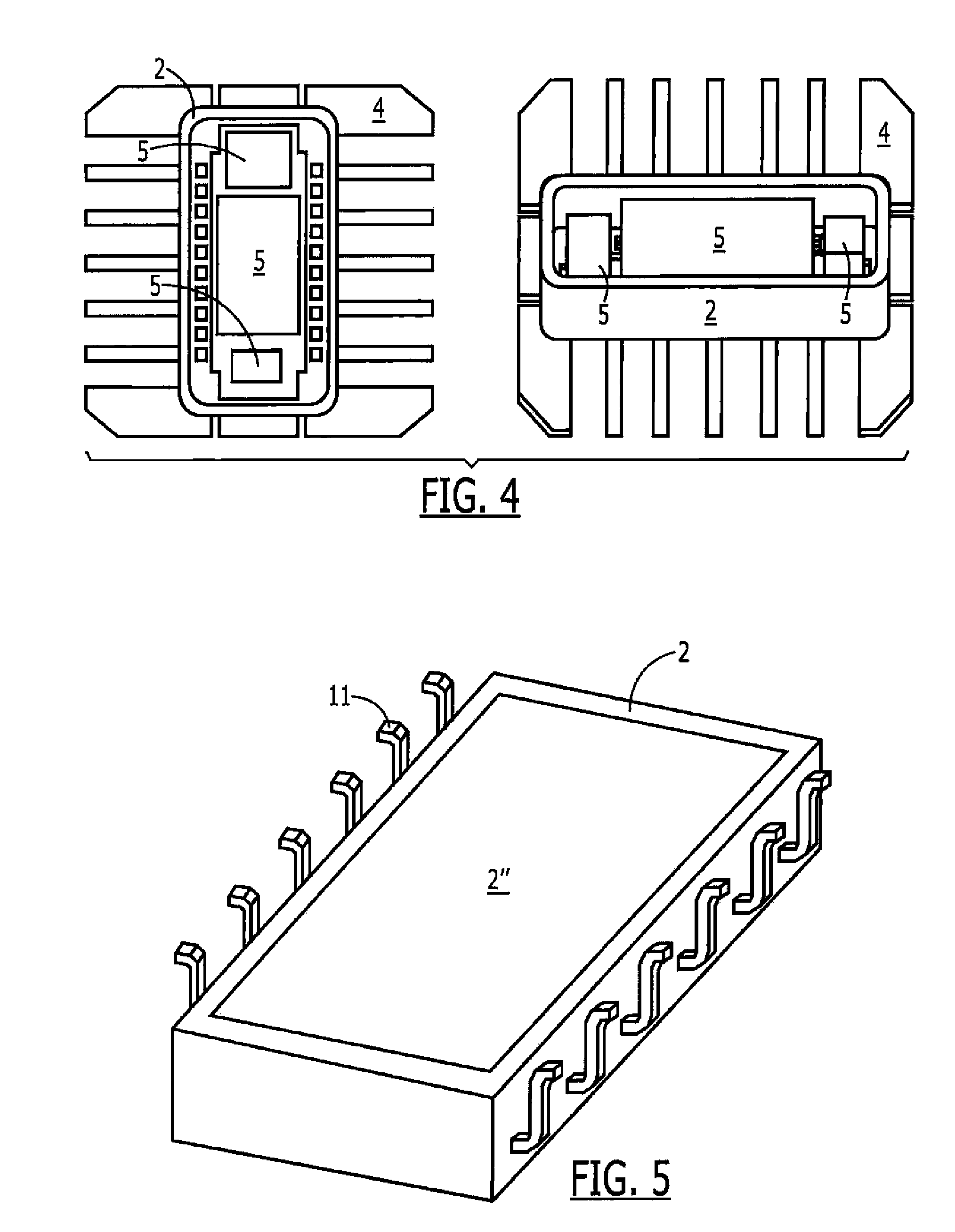
[0023]Identical parts are always provided with identical reference numerals in the various figures and are therefore typically also only labeled once.

[0024]FIG. 1 shows a side view of a module 1 according to an example embodiment of the present invention, module 1, preferably a sensor module and particularly preferably an acceleration sensor or speed sensor, having a module housing 2, a carrier element 3, a connection element 4, and at least one component 5, and module housing 2 completely enclosing the at least one component 5 and being situated on carrier element 3, and furthermore the at least one component 5 being mounted on connection element 4 and being situated between connection element 4 and carrier element 3. Furthermore, connection element 4 includes a closed and conductive protective face 8 in an overlap area with the at least one component 5 parallel to surface normal 10 of carrier element 3, protective face 8 being provided lying at a fixed electrical potential in part...


PUM

PropertyMeasurementUnit
areaaaaaaaaaaa
electrically conductiveaaaaaaaaaa
conductiveaaaaaaaaaa

Abstract

A module, in particular a sensor module, has a module housing, a carrier element, a connection element, and at least one component, the module housing completely enclosing the at least one component and being situated on the carrier element, and the at least one component also being mounted on the connection element and being situated between the connection element and the carrier element.

Description

CROSS-REFERENCE TO RELATED APPLICATIONS[0001]The present application claims priority to Application No. 10 2007 033 005.9, filed in the Federal Republic of Germany on Jul. 16, 2007, which is expressly incorporated herein in its entirety by reference thereto.FIELD OF THE INVENTION[0002]The present invention is directed to a module and to a method for producing a module.BACKGROUND INFORMATION[0003]Certain modules are conventional. For example, a sensor module is described in German Published Patent Application No. 103 52 002, the sensor module having a housing main body, a lead frame extending through the housing main body having leads, and a sensor configuration having at least one sensor chip. The sensor chip is mounted on the housing main body, which has a cover made of conductive material for EMC shielding. It has the disadvantage that the cover must be manufactured in a comparatively complex and time-consuming production and mounting method having low manufacturing tolerance, int...

Claims


Application Information

Patent Timeline
Patent Type & Authority Patents(United States)
IPC IPC(8): H05K9/00
CPCG01P1/023H01L23/057Y10T29/49002H01L2224/32245H01L2924/0002H01L2924/00
Inventor HUND, PAULIRSLINGER, HANS-MARTINJOBERT, TRISTANBAER, HANS-PETER
Owner ROBERT BOSCH GMBH
Why Eureka
Try Eureka