
Modulatable radiation collimator

a radiation collimator and modulation technology, applied in radiation therapy, diaphragm/collimeter handling, therapy, etc., can solve the problems of not being able to easily modulate, beam damage to healthy surrounding tissue, and patients can have serious side effects, etc., to achieve the effect of high resolution and rapid modulation

Active Publication Date: 2012-01-10
SIEMENS HEALTHCARE GMBH
View PDF16 Cites 7 Cited by
  • Summary
  • Abstract
  • Description
  • Claims
  • Application Information

AI Technical Summary

Benefits of technology

The invention is a beam collimator that has a higher resolution and can be quickly modulated. It includes absorber channels arranged adjacent to each other which form a two-dimensional collimator aperture in the form of a matrix. The collimator can be used in an x-ray therapy apparatus to provide high-resolution, easy-to-modulate, and fast-acting beam collimation. The collimator aperture can be partially or fully closed to reduce the surface dose and maintain the depth effect when irradiating a human body. The first absorber elements can be embodied in the manner of a truncated pyramid or cone, and the second absorber elements can be fixedly or changeably positioned to provide a high-packing density and high modulation speed. The collimator aperture can take the form of a partial surface of a sphere, which ensures maximum focused radiation can reach an object. The invention provides a solution for improving the accuracy and efficiency of beam collimation in various applications.

Problems solved by technology

It is nevertheless unavoidable that the beam also damages healthy surrounding tissue.
If the radiation is therefore not adequately restricted, the side effects for a patient can be serious.
The disadvantage of multileaf collimators is that the beam formation is restricted and undercut or hollow openings cannot be realized.
Furthermore, the continuous beam inside the beam cannot be influenced, in other words a dose profile can only be influenced at the beam edge.
Known types are also either very slow in adjusting the leaves or only allow two positions per leaf.

Method used


Image

  • Modulatable radiation collimator
  • Modulatable radiation collimator
  • Modulatable radiation collimator

Examples


Embodiment Construction

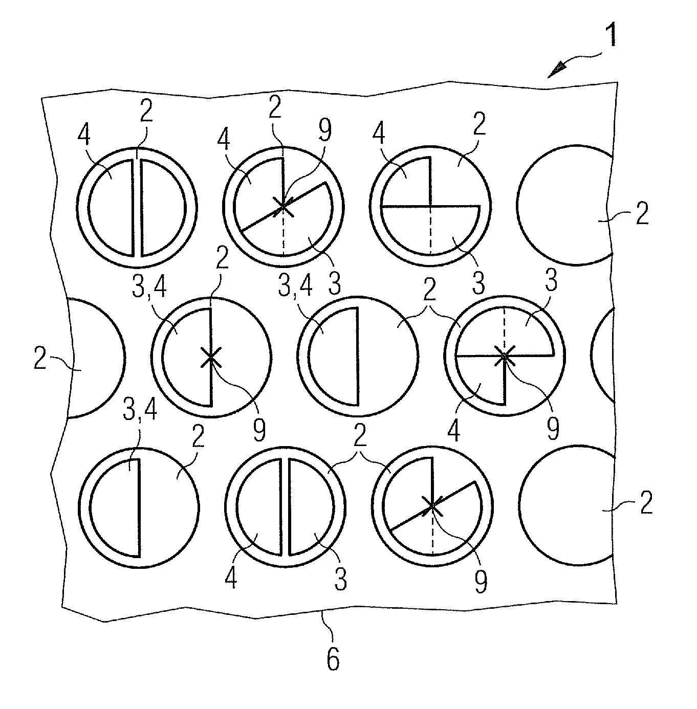
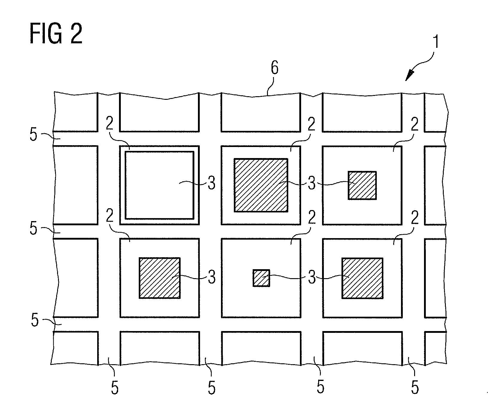
[0028]For reasons of clarity, the distances between webs 5 and the first and second absorber elements 3, 4 are in some cases shown in the FIGS. 1, 2 and 4 to 7. In one realization, these distances and / or “gaps” are not present. The first absorber elements 3 rest in a first position and the second absorber elements 4 always rest at least “tightly” against the webs 5. The first absorber elements 3 in the first position therefore do not allow radiation through the absorber channels 2.

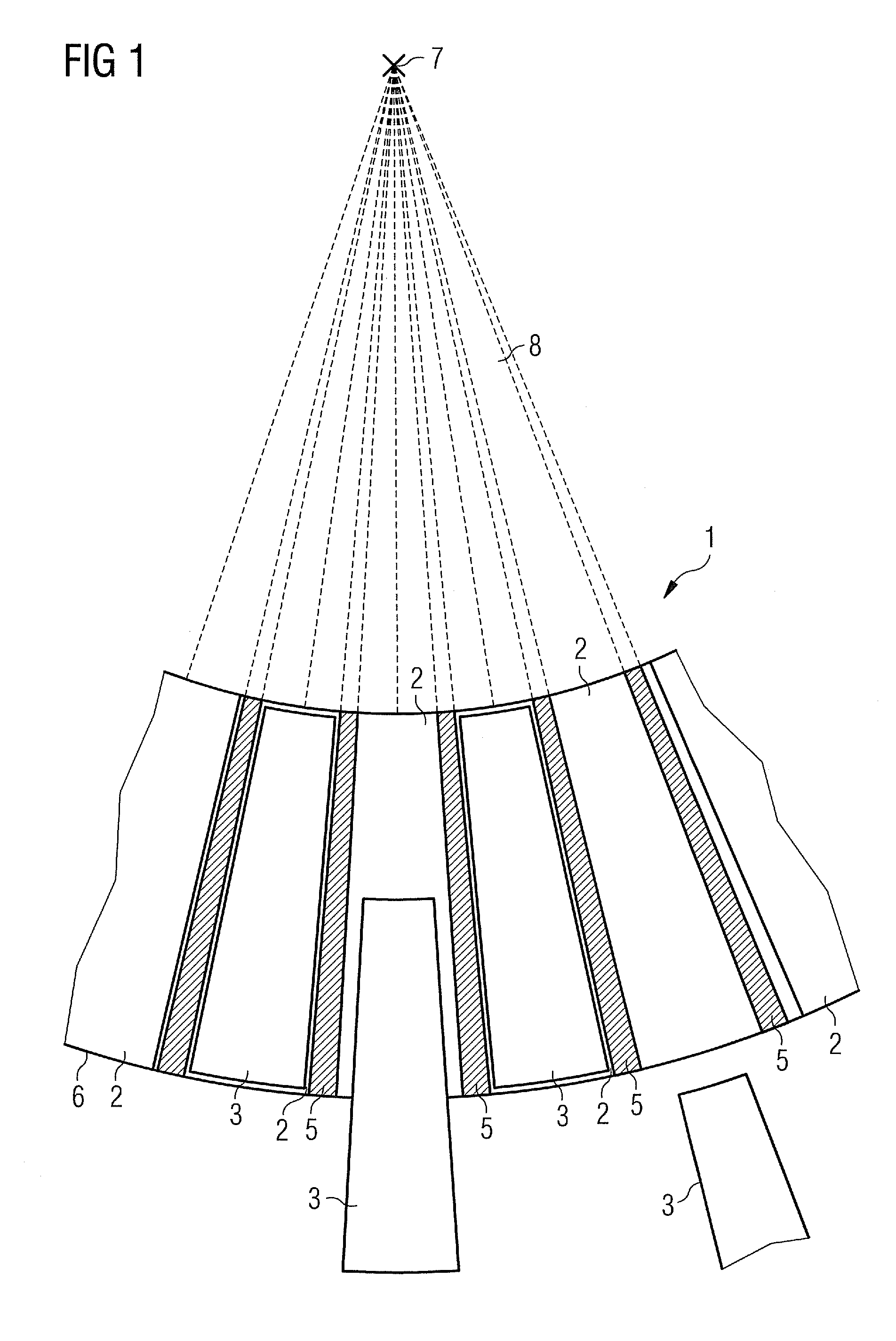
[0029]FIG. 1 shows an enlarged cutout from a radiation collimator 1 with a curved surface, which is arranged in the radiation field 8 of a radiation source 7. The object of the collimator 1 is to restrict, modulate and attenuate radiation. To this end, the collimator 1 forms a two-dimensional aperture, which can be modulated by the subject matter of the invention.

[0030]The radiation collimator 1 includes a support 6 with a plurality of absorber channels 2, which are directed at the focal point of the radia...


PUM


Abstract

The invention specifies a radiation collimator, in particular an x-ray collimator, which can be arranged between a radiation source outputting radiation and an object. The radiation collimator includes absorber channels arranged adjacent to one another which form a two-dimensional collimator aperture in the form of a matrix and a first absorber element arranged in the absorber channel. The first absorber element blocks the radiation in a first position and allows the radiation at least partially through the absorber channel in at least one second position. The first absorber element is rod-shaped and can be moved in the absorber channel by a rotation about its longitudinal axis and / or by a longitudinal and / or transverse displacement from the first into the at least one second position. This is advantageous in that the two-dimensional collimator aperture can be modulated easily, rapidly and with high resolution.

Description

CROSS REFERENCE TO RELATED APPLICATIONS[0001]This application claims priority of German application No. 10 2008 055 921.0 filed Nov. 5, 2008, which is incorporated by reference herein in its entirety.FIELD OF THE INVENTION[0002]The invention relates to a radiation collimator for use in beam therapy and to the use of a radiation collimator in radiation therapy.BACKGROUND OF THE INVENTION[0003]Radiation therapy is routinely used to treat invasive medical diseases such as cancer for instance. The principle behind beam therapy consists in an x-ray beam killing off cancerous cells. If the beam is directed at a cancer tissue or another abnormal area, the cells are destroyed. It is nevertheless unavoidable that the beam also damages healthy surrounding tissue. If the radiation is therefore not adequately restricted, the side effects for a patient can be serious.[0004]A restriction of this type is usually achieved by collimating the beam, so that it only expands across the minimal required ...

Claims


Application Information

Patent Timeline
Patent Type & Authority Patents(United States)
IPC IPC(8): G21K1/04G21K1/02
CPCG21K1/04G21K1/046A61N5/1042
Inventor HEID, OLIVER
Owner SIEMENS HEALTHCARE GMBH
Learn More