Transfer device and image forming apparatus using the same

a technology of transfer device and image forming apparatus, which is applied in the direction of electrographic process apparatus, instruments, optics, etc., can solve the problems of roller members being prone to run up on beads, the belt skewing problem of the intermediate transfer belt during circulatively, and the variation of the expansion coefficient of the belt, so as to prevent the guide element from peeling off, secure the necessary strength, and reduce the damage to the tip

Active Publication Date: 2012-01-10
SHARP KK
View PDF6 Cites 33 Cited by
  • Summary
  • Abstract
  • Description
  • Claims
  • Application Information

AI Technical Summary

Benefits of technology

[0017]The present invention has been devised in view of the above problems, it is therefore an object of the present invention to provide a transfer device that uses an intermediate transfer belt and that can inhibit damage to, and peeling of, the guide elements for guiding conveyance of the intermediate transfer belt so as to prevent the intermediate transfer belt from skewing, and hence can realize high-quality image forming as well as providing an image forming apparatus using the transfer device.

Problems solved by technology

However, the thus formed intermediate transfer belt will present variation in expansion coefficient from one point to another because of uneven distribution of the resin material and the conductive components mixed in the resin material.
Accordingly, the intermediate transfer belt suffers the problem of the belt skewing during circulatively traveling due to the difference in circumference depending on the points across the belt width and due to variation in dimensional accuracy and attachment accuracy of the roller members (drive roller, driven roller, etc.) that support and stretch the intermediate transfer belt.
However, if the positioning mark of bead 6610 is formed by perpendicular surface 6611a and 6612a alone, there occurs the problem that the roller members are prone to run up on bead 6610.
There is also another problem that if the positioning mark of bead 6610 collides with the endface of the roller member, the edges of the positioning mark are prone to deform and peel off.

Method used


Image

  • Transfer device and image forming apparatus using the same
  • Transfer device and image forming apparatus using the same
  • Transfer device and image forming apparatus using the same

Examples


first embodiment

The First Embodiment

[0051]The first embodiment of the present invention will hereinafter be described in detail with reference to the accompanying drawings.

[0052]FIG. 3 shows one exemplary embodiment of the invention, or is an illustrative view showing an overall configuration of an image forming apparatus using a transfer device according to the first embodiment of the present invention.

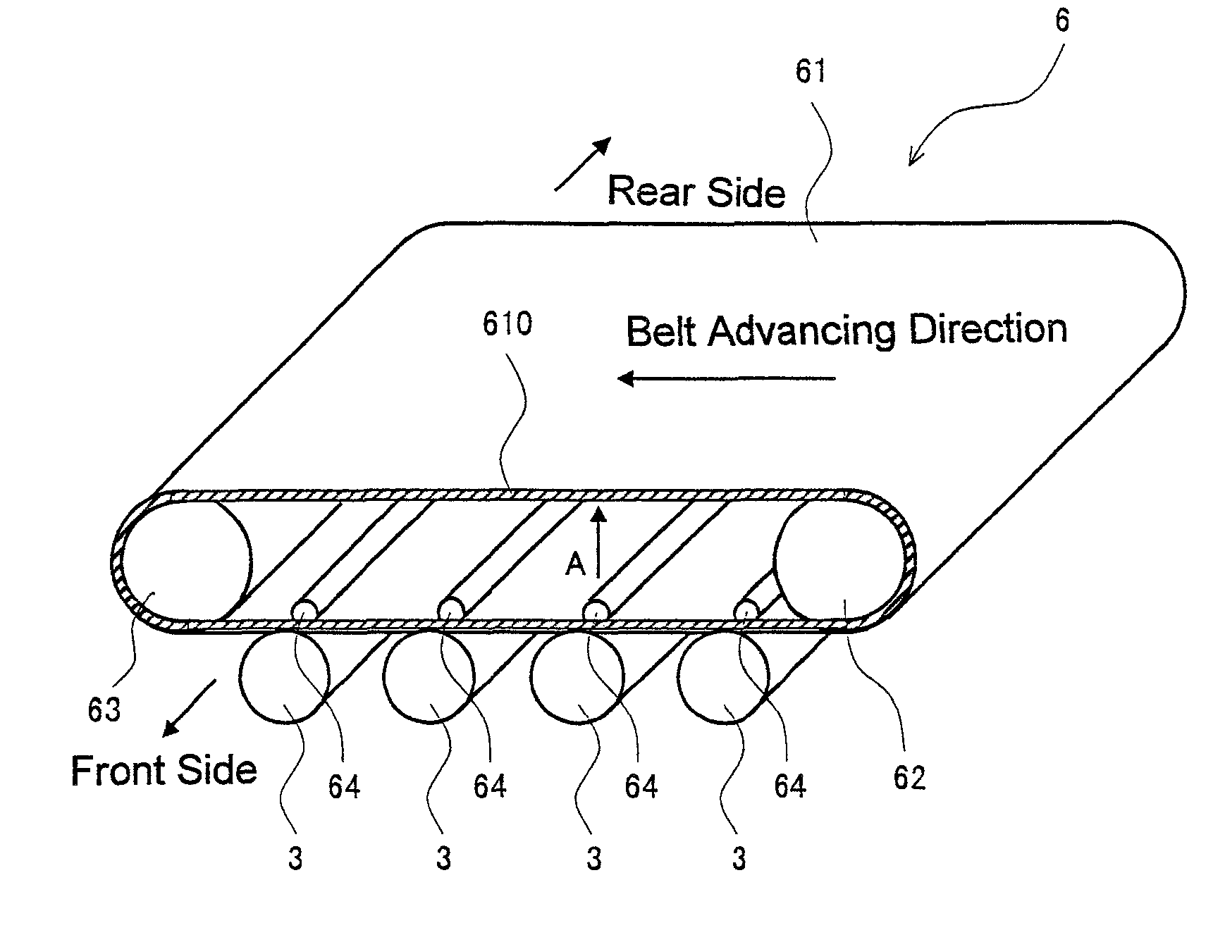
[0053]An image forming apparatus 100 according to the first embodiment for forming images using toner based on electrophotography, including: as shown in FIG. 3, photoreceptor drums 3 on which electrostatic latent images are formed; chargers (charging devices) 5 for electrifying the photoreceptor drum 3 surfaces; an exposure unit (exposure system) 1 for forming electrostatic latent images on the photoreceptor drum 3 surfaces; developing devices 2 for forming toner images by supplying the photoreceptor drum 3 surfaces with toners; transfer portion (transfer device) 6 for transferring the toner images...

second embodiment

The Second Embodiment

[0132]Next, the drawings of the second embodiment of the present invention will be described in detail with reference to the drawings.

[0133]FIG. 11 is an illustrative view showing a configuration of a guide element according to the second embodiment of the present invention.

[0134]Since the transfer device using the guide elements according to the second embodiment and the image forming apparatus using this transfer device have the same configurations as the transfer portion 6 and image forming apparatus 100 of the first embodiment excepting the configuration of the guide elements, description for those is omitted.

[0135]Similarly to guide element 610 of the first embodiment, a guide element 2610 according to the second embodiment is provided annularly on endless intermediate transfer belt 61 so that the first and second ends, designated at 2611 and 2612 are opposed to each other with a predetermined distance apart therebetween, as shown in FIG. 11. However, first...

##al example 1

Variational Example 1

[0151]Variational example 1 has the same configuration as that of FIG. 11 except in that no fourth inclined surface 2611c is formed.

[0152]As shown in FIG. 12, in a guide element 3610 of variational example 1, the first and second ends, designated at 3611 and 3612 are arranged so as to oppose each other with a predetermined distance apart therebetween. No inclined surface is formed between the perpendicular surface at the distal side of first end 3611 and the outside surface while a third inclined surface 3612c that is inclined relative to the belt advancing direction is formed between the perpendicular surface 3612a1 on the guide surface 3612s2 side of second end 3612 and guide surface 3612s2.

[0153]With this configuration, it is possible to omit the step of forming fourth inclined surface 2611c of FIG. 11 and inhibit guide element 3610 from running up on the roller members without lowering the strength of other parts.


PUM


Abstract

The transfer portion for use in an image forming apparatus includes: an intermediate transfer belt having a toner image temporarily transferred from a photoreceptor drum; roller members that support and stretch the intermediate transfer belt; and strip-like guide elements that guide conveyance of the intermediate transfer belt. The guide elements are provided on the inner peripheral surface of the intermediate transfer belt with the first and second ends opposed to and arranged a predetermined gap apart from each other. Each of the first and second ends is formed with a first (second) perpendicular surface that is perpendicular to the advancing direction of the belt and a first (second) inclined surface that is inclined relative to the belt advancing direction. The first and second perpendicular surfaces are formed in such a position that the first and second ends become tapered by the first and second inclined surfaces, respectively.

Description

[0001]This Nonprovisional application claims priority under 35 U.S.C. §119 (a) on Patent Application No. 2009-138796 filed in Japan on 10 Jun. 2009, the entire contents of which are hereby incorporated by reference.BACKGROUND OF THE INVENTION[0002](1) Field of the Invention[0003]The present invention relates to a transfer device and an image forming apparatus using the same, and in particular relates to a transfer device which is used in an image forming apparatus such as an electrostatic copier, laser printer, facsimile machine or the like that forms images with toner based on electrophotography and which transfers the toner image formed on the peripheral side of an image bearer by means of an endless belt as well as to an image forming apparatus using the same device.[0004](2) Description of the Prior Art[0005]Conventionally, image forming apparatuses based on electrophotography such as copiers, printers, facsimile machines and the like have been known. In these image forming appa...

Claims


Application Information

Patent Timeline
Patent Type & Authority Patents(United States)
IPC IPC(8): G03G15/01
CPCG03G15/1605G03G2215/00151
Inventor NAKAMURA, GINGA
Owner SHARP KK
Why Eureka
Try Eureka