Conveyor-belt apparatus and image heating apparatus changing the belt tension in accordance with the moving state of the belt

a technology of conveyor belts and belt tensioners, which is applied in the direction of electrographic process apparatus, instruments, optics, etc., can solve the problems of enlargement of the main body of the image forming apparatus, damage at the right and left ends of the belt, and movement becomes marked, so as to prevent enlargement of the apparatus and control lateral movement.

Inactive Publication Date: 2012-01-10
CANON KK
View PDF9 Cites 7 Cited by
  • Summary
  • Abstract
  • Description
  • Claims
  • Application Information

AI Technical Summary

Benefits of technology

[0011]It is an object of the present invention to provide a conveyor-belt apparatus in which, while preventing enlargement of the apparatus, lateral movement control of a belt may be properly carried out even if friction pressure distribution is varied due to a friction factor (μ) on an inner surface of the belt. Further, it is another object of the invention to provide an image heating apparatus using such a conveyor-belt apparatus described above.

Problems solved by technology

However, in such a case, the fixing device is enlarged in size, resulting in a problem of enlargement in size of the image forming apparatus main body.
However, even in the belt type of apparatus, there is the following problem in spite of those advantages.
Specifically, the belt moves alternately to right and left to be misaligned to perform serpentine movement in the belt width direction, which is orthogonal to a circulation direction, resulting in the dropping out of a belt driving roller, likely causing damage at right and left ends of the belt.
However, if the durability of the belt is lowered or the belt is degraded due to use with time, there occurs a variation in friction pressure distribution due to a friction factor (μ) on an inner surface of the belt, resulting in a tendency for the belt to conduct the lateral movement toward a side where the friction pressure is lowered.
This tendency of lateral movement becomes marked and the belt finally becomes out of control.
The belt, being out of control, comes off from the roller members to drop out or to be damaged, and reaches the end of its life.
In such a case of the image forming apparatus, which is required to severly limit the space for installing components, it is particularly and significantly disadvantageous.
For example, in a case of twin belt fuser (TBF), particularly, there is employed a two-axis steering mechanism using two roller members at an entry of an upstream side in a direction of conveying the recording sheet, and there is a limit to increase the steering amount because the increase of the steering amount affects the behavior of the recording paper.

Method used


Image

  • Conveyor-belt apparatus and image heating apparatus changing the belt tension in accordance with the moving state of the belt
  • Conveyor-belt apparatus and image heating apparatus changing the belt tension in accordance with the moving state of the belt
  • Conveyor-belt apparatus and image heating apparatus changing the belt tension in accordance with the moving state of the belt

Examples


first embodiment

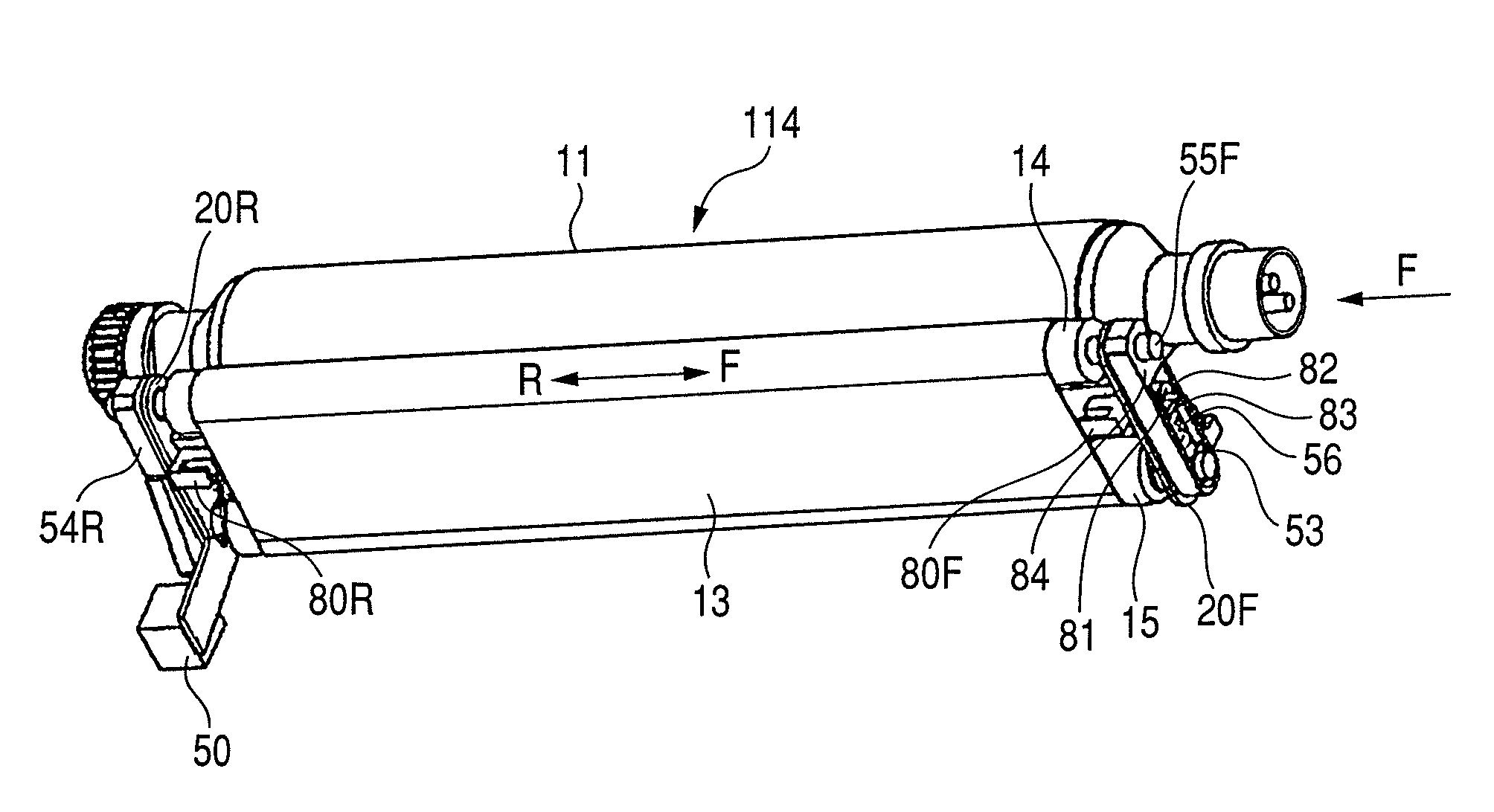
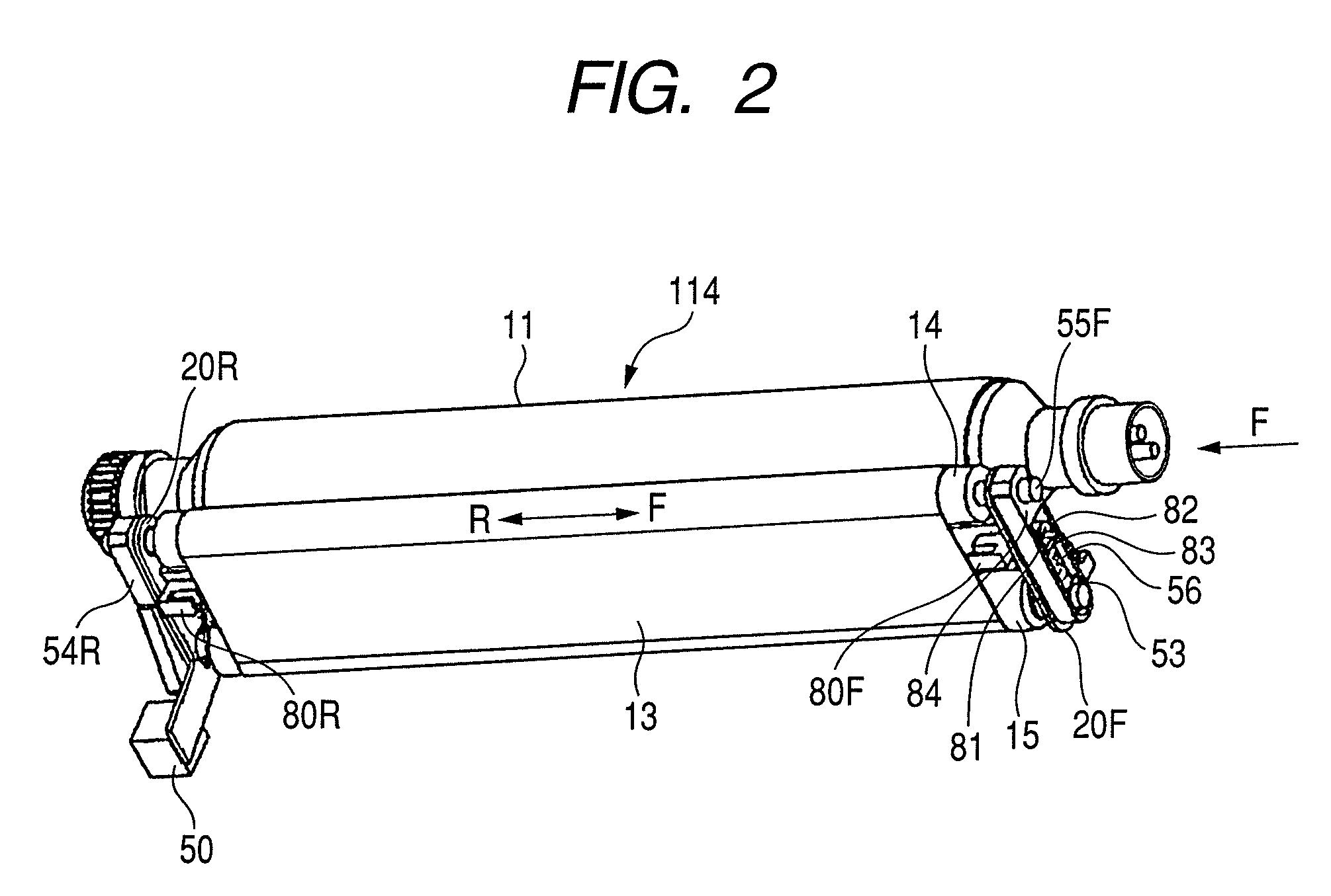
[0048]Next, by referring to FIG. 2 to FIG. 6, a description will be provided of a first embodiment of a case where a conveyor-belt apparatus according to this embodiment is applied to a fixing device 114 as a toner image heating apparatus of this embodiment.

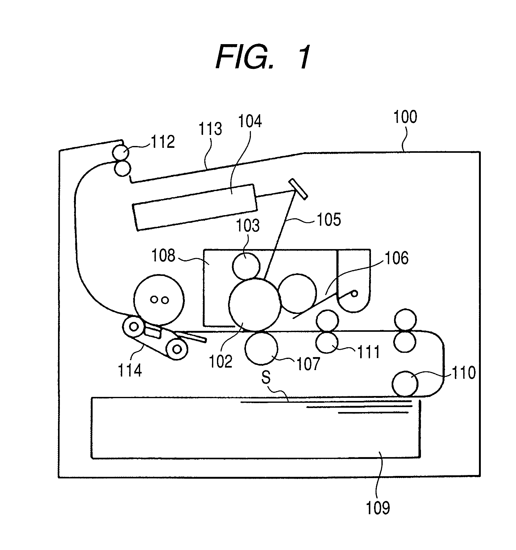
[0049]The fixing device 114 includes a heating roller 11 inside of which a halogen heater 12 is mounted. Owing to the heat of the halogen heater 12, the heating roller 11 heats an unfixed toner image transferred onto the sheet S. A pressure belt (endless belt) 13, which constitutes the conveyor-belt apparatus, nips a conveying sheet S by a nip portion between the heating roller (rotary member) 11 and the pressure belt 13 to convey the sheet S while applying pressure to the sheet S at an appropriate nip pressure. The heating roller 11 includes a metal core formed of an aluminum cylindrical pipe having an outer diameter of 56 mm and an inner diameter of 50 mm, for instance, and the halogen heater 12 is provided inside the metal cor...

second embodiment

[0089]Next, referring to FIG. 11 to FIG. 17, a description will be provided of a second embodiment of a case where a conveyor-belt apparatus according to this embodiment is applied to a fixing device 114 as a toner image heating apparatus of this embodiment.

[0090]In the second embodiment, instead of the heating roller (third rotation member) 11 according to the first embodiment, an endless heating belt 30 is provided as illustrated in FIG. 12. It is an aim to make the apparatus further compact, and to make the nip width wider with an employment of the heating belt 30. Then, in the second embodiment, belt sensors 90R and 90F each provided to both ends in the width direction of the heating belt 30, for which the lateral movement control is performed, may detect three positions (R1, R2, Re, F1, F2, and Fe) each provided in the width direction of the heating belt 30. With this structure, the lateral movement control may be simplified compared with the first embodiment.

[0091]In FIG. 12, ...


PUM


Abstract

A conveyor-belt apparatus includes a belt, a supporting member that rotatably supports the belt, a moving unit that displaces at least one end of the supporting member in a longitudinal direction to move the belt in the longitudinal direction, and a tension changing unit that changes a tension of the belt in accordance with the moving state of the belt in the longitudinal direction when the moving unit displaces the end of the supporting member.

Description

BACKGROUND OF THE INVENTION[0001]1. Field of the Invention[0002]The present invention relates to a conveyor-belt apparatus in which an endless belt circulates. Further, the present invention relates to an image heating apparatus in which the conveyor-belt apparatus may be applicable to, for example, a fixing device for heating a toner image in an image forming apparatus such as a copying machine or a printer.[0003]2. Description of the Related Art[0004]In general, in the image forming apparatus, a toner image formed on an image bearing member is transferred onto a sheet such as a recording material, and the sheet is conveyed to the fixing device in which the toner image is heated and pressed to be fixed onto the sheet, thereby recording and outputting the image. A typical fixing device is constructed of a roller pair including a heating roller and a pressure roller. A heater is installed inside the heating roller, and the pressure roller is brought into pressure-contact with the hea...

Claims


Application Information

Patent Timeline
Patent Type & Authority Patents(United States)
IPC IPC(8): G03G15/20
CPCG03G15/206G03G2215/2009
Inventor CHIBA, TAKATOSHI
Owner CANON KK
Why Eureka
Try Eureka