Vehicle charging system, vehicle charging device and electric vehicle

a charging system and vehicle technology, applied in the direction of indirect heat exchangers, battery/fuel cell control arrangements, light and heating apparatus, etc., can solve the problems of poor sound insulation and design, poor passenger comfort, and the provision of an exhaust hole as in the electrically-driven moving body, so as to ensure passenger comfort. the effect of

Active Publication Date: 2012-01-17
TOYOTA JIDOSHA KK
View PDF20 Cites 45 Cited by
  • Summary
  • Abstract
  • Description
  • Claims
  • Application Information

AI Technical Summary

Benefits of technology

[0009]According to this aspect, the heat medium for temperature management of the temperature change element is supplied to the electric vehicle in addition to the external power supply for charging the power storage device. Furthermore, the heat medium having been used to maintain the temperature of the temperature change element is discharged outside the vehicle through the heat medium discharge conduit. Therefore, retention of the used heat medium in a vehicle compartment space can be avoided. As a result, the passenger comfort is ensured and the power storage device can be charged by the external power supply while temperature changes caused by charging are managed.
[0013]More preferably, the electric vehicle further includes a vehicle compartment air path configured to communicate with the heat medium path, for taking in and delivering vehicle compartment air to the temperature change element, and an entry suppression mechanism for suppressing entry of the heat medium supplied through the heat medium path into the vehicle compartment space through the vehicle compartment air path.
[0016]According to this aspect, the heat medium for temperature management of the temperature change element can be supplied in addition to the external power supply for charging the power storage device. Furthermore, the heat medium having been used to maintain the temperature of the temperature change element is discharged outside the vehicle through the heat medium discharge conduit. Therefore, retention of the used heat medium in a vehicle compartment space can be avoided. As a result, the passenger comfort is ensured and the power storage device can be charged by the external power supply while temperature changes caused by charging are managed.
[0020]According to this aspect, the external power supply is supplied through the connector portion and the heat medium is supplied through the same connector portion. The supplied heat medium passes through the heat medium path formed to be separated from the vehicle compartment space, and heat exchange is performed between the temperature change element and the heat medium. And then, the heat medium is discharged outside the vehicle through the discharge opening in the connector. Therefore, retention of the heat medium having been used to maintain the temperature of the temperature change element in the vehicle compartment space can be avoided. As a result, the passenger comfort is ensured and the power storage device can be charged by the external power supply while temperature changes caused by charging are managed.
[0021]Preferably, the electric vehicle further includes a vehicle compartment air path configured to communicate with the heat medium path, for taking in and delivering vehicle compartment air to the temperature change element, and an entry suppression mechanism for suppressing entry of the heat medium supplied through the heat medium path into the vehicle compartment space through the vehicle compartment air path.

Problems solved by technology

Therefore, the provision of an exhaust hole as in the electrically-driven moving body disclosed in above-described Japanese Patent Laying-Open No. 08-037705 is not easy in terms of sound insulation and design.
Thus, in a case where a heat medium (such as cold air) is supplied from outside the vehicle, the used heat medium that is to be discharged stays around the power storage device and the passenger comfort is degraded.

Method used


Image

  • Vehicle charging system, vehicle charging device and electric vehicle
  • Vehicle charging system, vehicle charging device and electric vehicle
  • Vehicle charging system, vehicle charging device and electric vehicle

Examples


Embodiment Construction

[0029]The embodiments of the present invention will be described in detail with reference to the drawings. The same or corresponding portions in the drawings are represented by the same reference characters, and the description thereof will not be repeated.

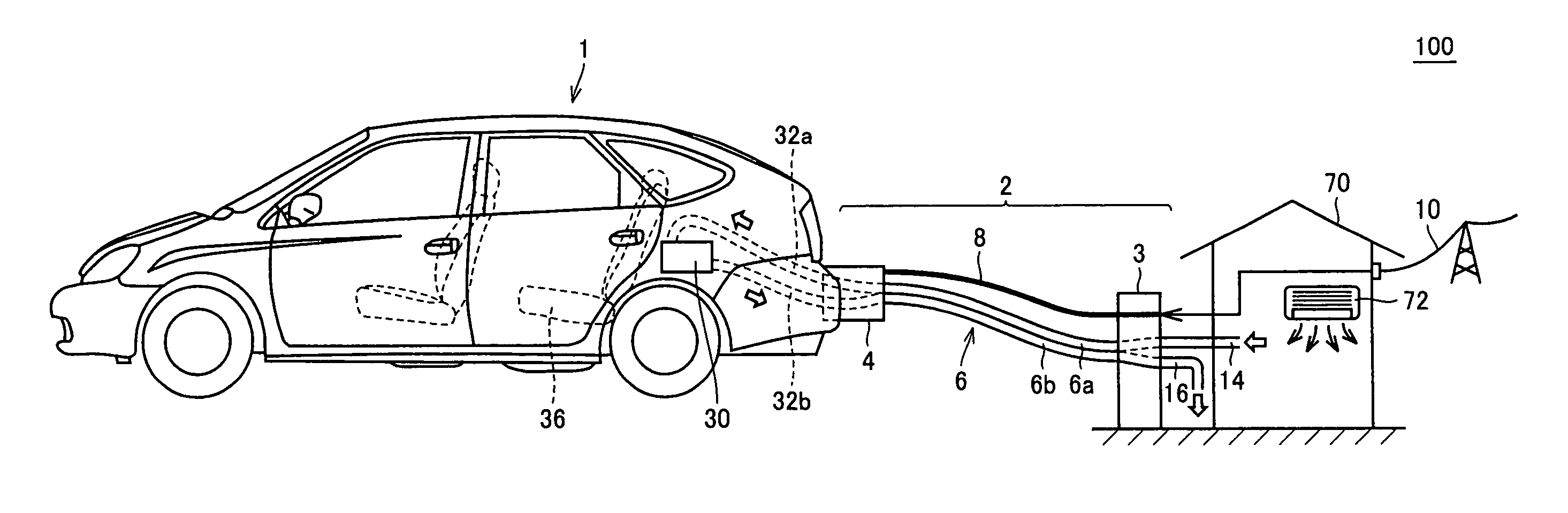
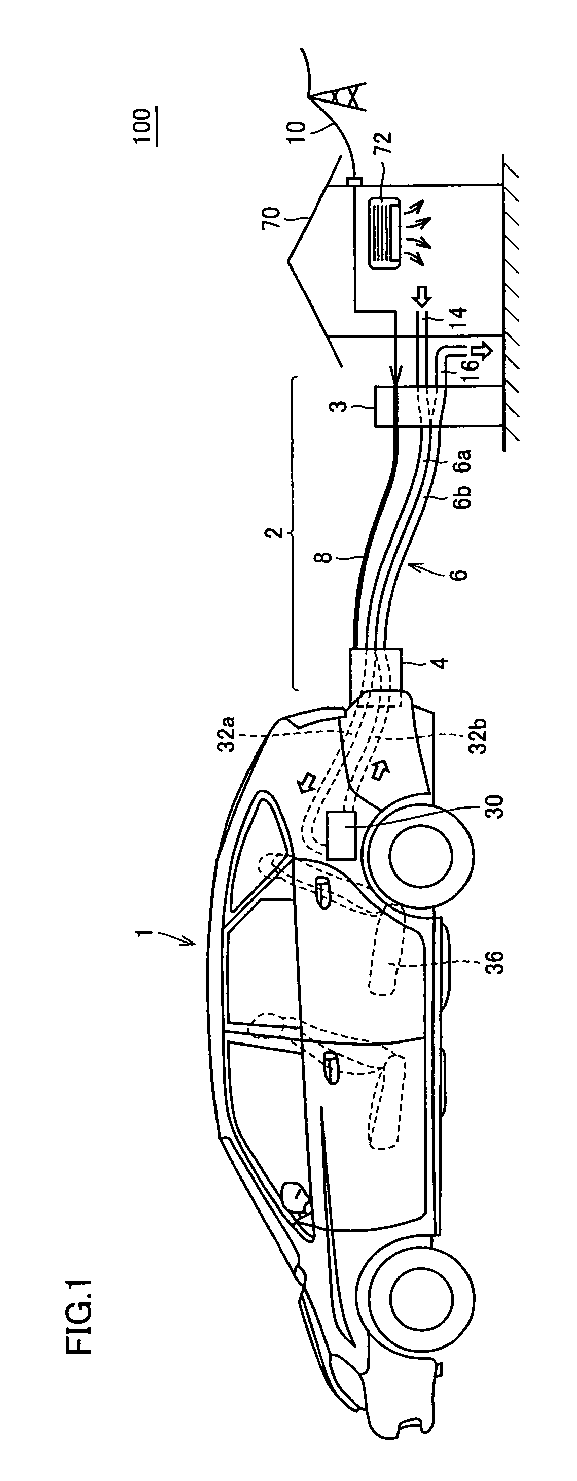
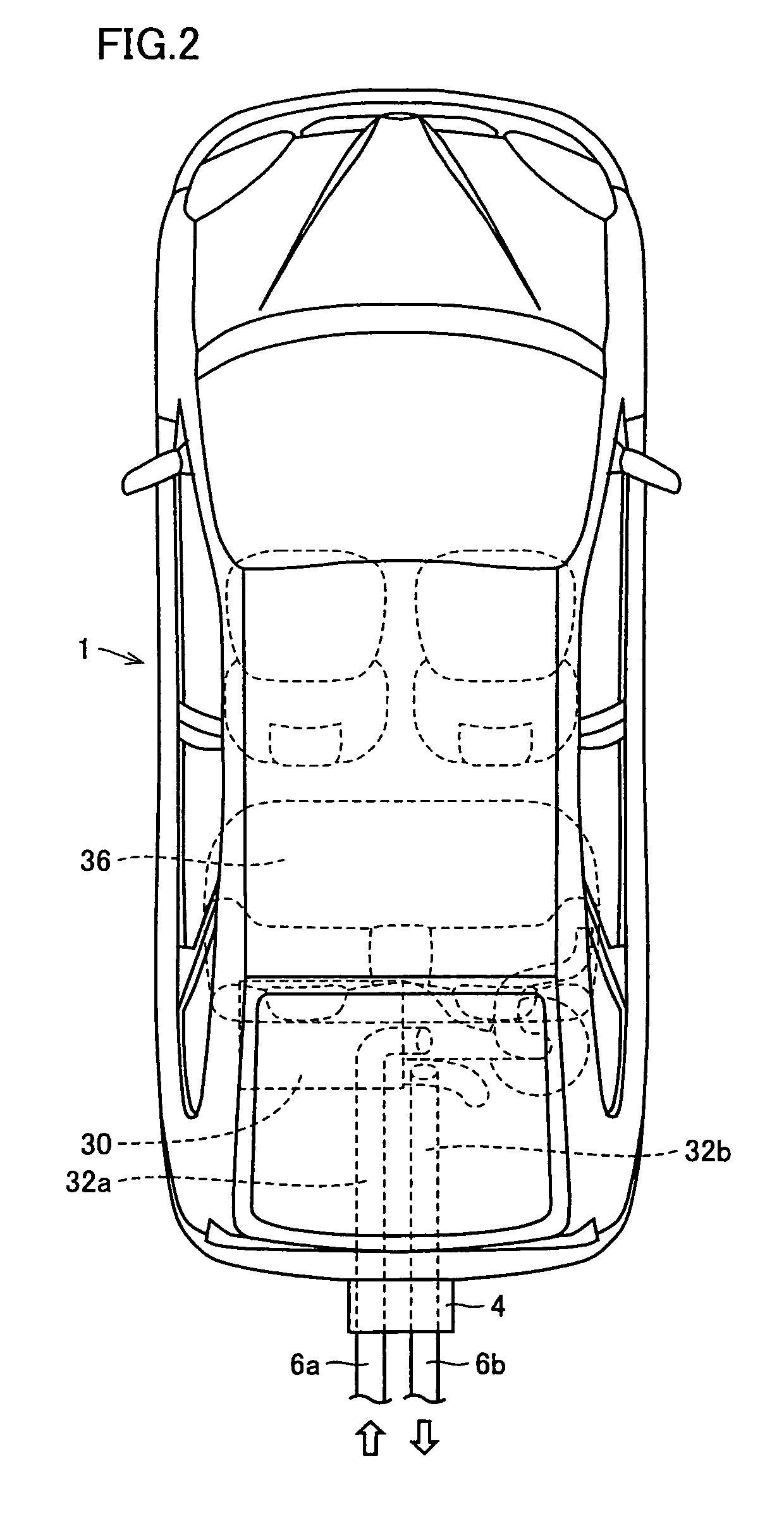
[0030]Referring to FIG. 1, a vehicle charging system 100 according to an embodiment of the present invention includes an electric vehicle 1 and a vehicle charging device 2.

[0031]Electric vehicle 1 is a hybrid vehicle by way of example and is equipped with a power supply unit 30. Power supply unit 30 is mainly a unit for supplying electric power to a motor that drives electric vehicle 1, and is configured to include a power storage device configured to be rechargeable as well as accessory electrical equipment. The power storage device is not limited to a secondary battery, but may be a fuel cell, a capacitor or the like. In a case where the power storage device is a secondary battery, the power storage device may be any of a lead-a...


PUM


Abstract

When a connector portion is coupled, switching dampers block a vehicle compartment air intake duct and a vehicle compartment air discharge duct, respectively. By a blowing fan, the air-conditioned air supplied through an air-conditioned air supply conduit flows through an outside air intake duct, a power supply unit, an outside air discharge duct, and an air-conditioned air discharge conduit in turn, and cools a battery.

Description

TECHNICAL FIELD[0001]The present invention relates to a technique for charging a power storage device, mounted on an electric vehicle and configured to be rechargeable by an external power supply. More particularly, the present invention relates to a technique for managing temperature changes caused by charging.BACKGROUND ART[0002]So-called electric vehicles such as battery vehicles, hybrid vehicles or fuel cell vehicles are equipped with a power storage device made up of a secondary battery, a capacitor or the like, and generate a driving force from electric power stored in the power storage device through a motor.[0003]A configuration has been proposed in which the power storage device mounted on these electric vehicles is charged by an external power supply such as a system power supply or a solar cell. As for a hybrid vehicle, in particular, if the cost of charging by an external power supply is lower than that of electric power generation at an internal combustion engine mounte...

Claims


Application Information

Patent Timeline
Patent Type & Authority Patents(United States)
IPC IPC(8): H02J7/00
CPCB60L11/1816B60L11/1838B60L11/1874Y02T10/7005Y02T90/163Y02T90/121Y02T90/128Y02T90/14Y02T10/705Y02T10/7072B60L58/26B60L53/302B60L53/18B60L53/66Y02T10/70Y02T90/12Y02T90/16
Inventor TAGUCHI, TOMONARI
Owner TOYOTA JIDOSHA KK
Why Eureka
Try Eureka