Fixing apparatus

a technology of fixing apparatus and roller, which is applied in the direction of electrographic process apparatus, instruments, optics, etc., can solve the problems of deformation of the roller layer, forming depressions in the elastic layer of the roller, and returning to their original shap

Active Publication Date: 2012-01-17
SHARP KK
View PDF7 Cites 9 Cited by
  • Summary
  • Abstract
  • Description
  • Claims
  • Application Information

AI Technical Summary

Benefits of technology

[0019]Further, since the rotational driving force provided by the driving portion is transmitted via the swing lever and the one-way clutch to the pressure release cam, it is not necessary to particularly change the configuration of the driving portion itself (a gear unit, etc.); thus, the gear unit will not be complex.
[0021]Moreover, since the fixing apparatus includes a control portion that moves the swing lever so that the swing lever separates from the swing cam, the swing lever can be stopped from swinging. Further, the pressure release cam can be stopped from rotating, and the displacement support member and the second roller can also be stopped from being displaced. Moreover, at this time, without performing an operation to bring the second roller into and out of contact with the first roller, the driving portion can rotate the first and second rollers. Therefore, rotational driving of the first and second rollers and an operation to bring the second roller into and out of contact with the first roller can be switched and performed.

Problems solved by technology

However, since the pressure between the rollers is large, when the fixing apparatus is not used and the rollers are in a stopped state for a long time, the elastic layers of the rollers are left deformed and sometimes unable to return to their original shape, thus forming depressions in the elastic layers of the rollers.
Accordingly, when the output shaft of the driving motor is rotated backward, various rollers also rotate backward, which causes various problems.
However, since one-way clutches are mounted in the gear unit itself, the configuration of the gear unit becomes complex.

Method used


Image

  • Fixing apparatus
  • Fixing apparatus
  • Fixing apparatus

Examples


Embodiment Construction

[0032]Hereinafter, an embodiment of the present invention will be described in detail with reference to the accompanying drawings.

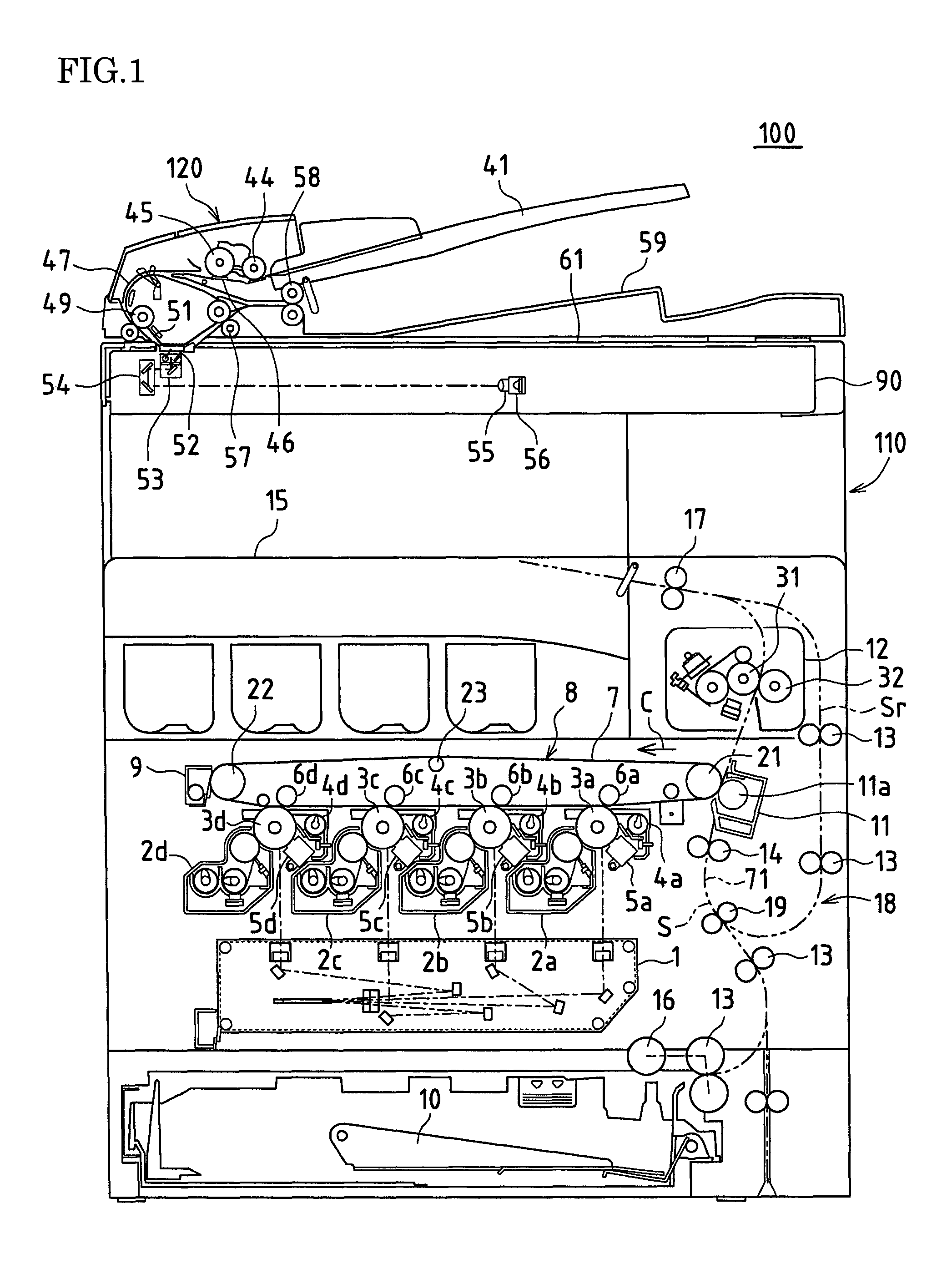
[0033]FIG. 1 is a cross-sectional view showing an image forming apparatus 100, which an embodiment of a fixing apparatus of the present invention has been applied to. The image forming apparatus 100 includes an original reading apparatus 120, which reads an original image, and an apparatus main body 110, which records and forms, on recording paper in color or in a single color, an original image read by the original reading apparatus 120 or an image received from outside.

[0034]In the original reading apparatus 120, when originals are set on an original setting tray 41, a pickup roller 44 is pressed against the surface of the originals and rotated. Then, the originals are drawn out from the original setting tray 41 and passed between a separation roller 45 and a separation pad 46 so as to be individually separated. Thereafter, the originals are transported...


PUM


Abstract

In one embodiment, when a hot roller is driven to rotate, a driving gear rotates so that a swing gear and a swing cam rotate. Then, a sliding contact edge on the right side of a swing lever that abuts against the circumferential face of the swing cam repeatedly moves up and down, and the swing lever repeatedly rotates clockwise and counterclockwise with a shaft of a pressure release cam as the center. At this time, since only the clockwise rotation of the swing lever is transmitted via a one-way clutch to the shaft of the pressure release cam, the clockwise rotation is intermittently transmitted to the shaft of the pressure release cam. As a result of this, the pressure release cam intermittently rotates clockwise, and the pressure release cam pushes away a roller of a displacement frame, so that the pressure roller separates from the hot roller.

Description

CROSS-REFERENCE TO RELATED APPLICATIONS[0001]This application claims priority under 35 U.S.C. §119(a) on Patent Application No. 2008-165968 filed in Japan on Jun. 25, 2008, the entire contents of which are herein incorporated by reference.BACKGROUND OF THE INVENTION[0002]1. Field of the Invention[0003]The present invention relates to a fixing apparatus that is applied in an image forming apparatus using an electrophotographic method, such as a copying machine, a facsimile, or a printer.[0004]2. Related Art[0005]In an image forming apparatus of this type using an electrophotographic method, an electrostatic latent image is formed on the surface of a photosensitive drum. Then, the electrostatic latent image on the surface of the photosensitive drum is developed using toner, and a toner image is thereby formed on the surface of the photosensitive drum. Thereafter, the toner image is transferred from the photosensitive drum onto recording paper, the recording paper is heated and pressed...

Claims


Application Information

Patent Timeline
Patent Type & Authority Patents(United States)
IPC IPC(8): G03G15/20
CPCG03G15/2032
Inventor TSUKAMOTO, KIMIHIDENAKAMURA, HIROKAZUYAMANAKA, TAKASHINAMISAKI, KOUSUKE
Owner SHARP KK
Why Eureka
Try Eureka