Workpiece vacuum chuck head

a technology for vacuum chucks and workpieces, applied in the field of workpiece vacuum chuck heads, can solve the problems of difficult difficult to manufacture vacuum chuck parts, and difficult to place such a workplace on or remove workpieces from placement surfaces, etc., to accurately and reliably vacuum chuck workpieces, accurately and reliably place workpieces, and achieve accurate and reliable vacuuming

Active Publication Date: 2012-01-24
HIRATA & CO LTD
View PDF16 Cites 3 Cited by
  • Summary
  • Abstract
  • Description
  • Claims
  • Application Information

AI Technical Summary

Benefits of technology

[0021]As mentioned above, the workpiece vacuum chuck head of the present invention can accurately and reliably vacuum-chuck a workpiece while following the inclination of the workpiece placement surface, and can accurately and reliably place the workpiece on the workpiece placement surface. Thus, the workpiece can be accurately and reliably placed on and removed from the workpiece placement surface. Also, since an excessive stress is not applied to the workpiece, the workpiece is not damaged. Furthermore, the workpiece vacuum chuck head has an integral structure and thus is structurally simplified. Also, the working of the follower mechanism section simplifies the operation of the workpiece vacuum chuck head, so that the workpiece vacuum chuck head exhibits excellent operability and reliability.
[0022]In the case where the workpiece pusher is accommodated in the negative-pressure chamber of the workpiece vacuum chuck head, and the workpiece pusher has the pin portion which is inserted into the suction hole and which projects beyond and retracts behind the workpiece vacuum chuck surface, the following advantageous effects can be attained. When the vacuum-chucked workpiece is placed on the workpiece placement surface, the workpiece vacuum chuck head follows the inclination of the workpiece placement surface, and reliably releases the vacuum-chucked workpiece by means of the pin portion pushing the workpiece. Therefore, the workpiece vacuum chuck head can accurately and reliably place the workpiece on the workpiece placement surface, thereby avoiding positional misalignment of the workpiece. Also, when the workpiece is vacuum-chucked, the workpiece vacuum chuck head follows the inclination of the workpiece placement surface, and the pin portion pushes the workpiece. Therefore, the workpiece vacuum chuck head can accurately and reliably vacuum-chuck the workpiece onto the workpiece vacuum chuck surface, thereby avoiding positional misalignment of the workpiece.
[0023]In the case where the structure of the follower mechanism section of the workpiece vacuum chuck head that is easily elastically deformable has the plurality of curved spring legs, and the plurality of curved spring legs connect the base section and the workpiece vacuum chuck section at a plurality of corresponding positions and allow the workpiece vacuum chuck surface to be uniformly displaced upon subjection to an external force of any direction that acts on the workpiece vacuum chuck surface, the structure of the follower mechanism section that is easily elastically deformable can be implemented through employment of a very simple configuration.

Problems solved by technology

It is not easy to accurately and reliably vacuum-chuck a light, minute workplace having a size on the order of several hundreds of micrometers to several millimeters, to reliably release the vacuum-chucked workplace, and to accurately and reliably place the released workpiece on a workplace placement surface, for the following reasons.
For an ordinary method of merely applying and releasing a holding force or a vacuum-chucking force, it is not easy to place such a workplace on or remove the workpiece from a placement surface.
Also, it is not easy to manufacture a vacuum chuck member in accordance with dimensions of such a workpiece and to accurately set the vacuum chuck member in accordance with the position and posture of the workpiece.
However, this device does not have a follower mechanism for causing the vacuum chuck surface to follow the workpiece placement surface.
However, the latter device does not have means for reliably releasing a vacuum-chucked workpiece from the nozzle tip.
However, this device is not intended to vacuum-chuck and attach a light, minute workpiece having a size on the order of several hundreds of micrometers to several millimeters and thus is not devised to handle such workplaces.Patent Document 1: Japanese Patent Application Laid-Open (kokai) No.

Method used


Image

  • Workpiece vacuum chuck head
  • Workpiece vacuum chuck head
  • Workpiece vacuum chuck head

Examples


embodiment

[0059]Next, an embodiment of the present invention will be described.

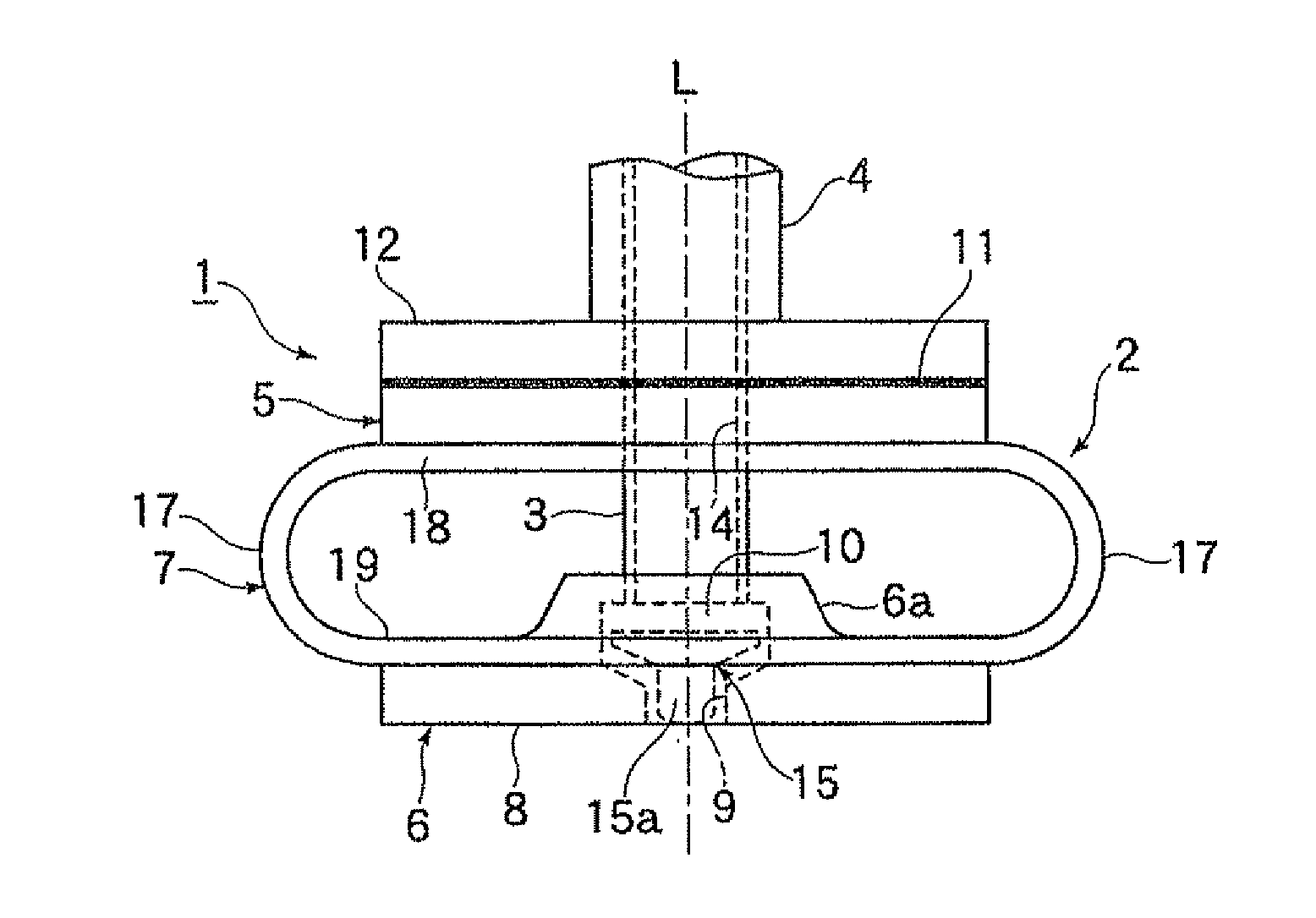
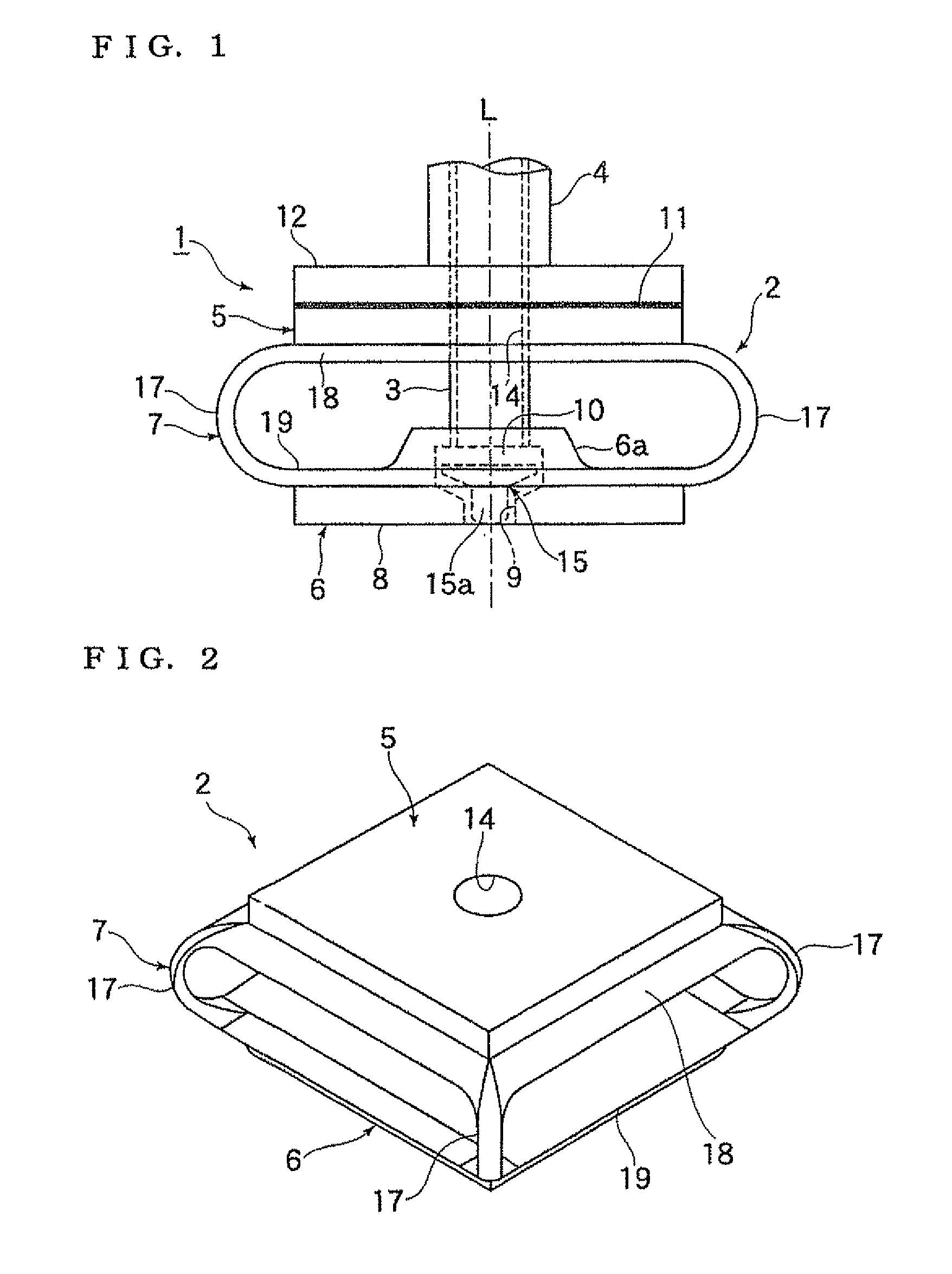
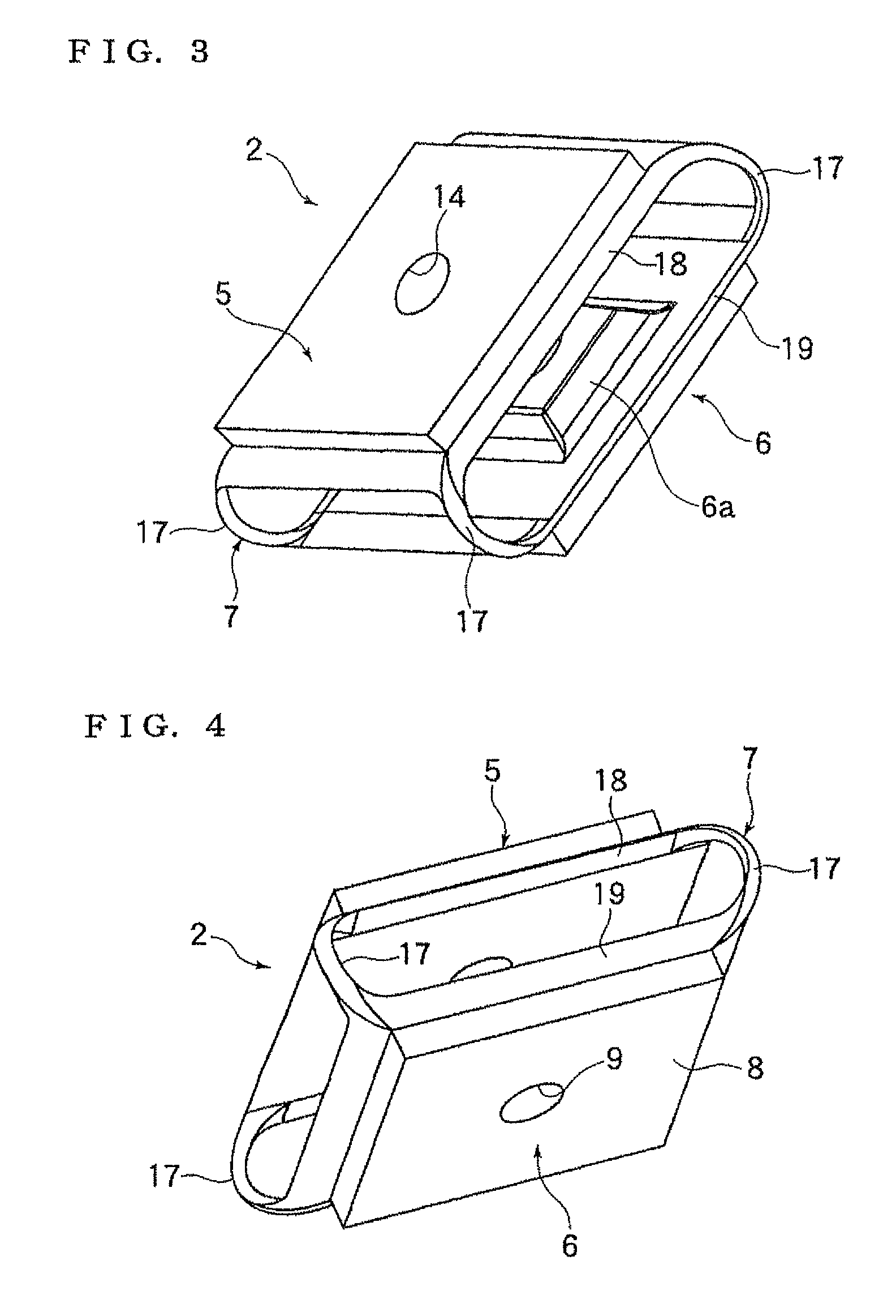
[0060]A workpiece vacuum chuck head of the present embodiment is used to vacuum-chuck a light, minute workpiece, such as an electronic component, and to release and place the vacuum-chucked workpiece on a workpiece placement surface, such as a substrate surface. The workpiece vacuum chuck head is roughly configured such that, as shown in FIG. 1, a communication pipe 3 extending to a vacuum source is connected to a workpiece vacuum chuck head body 2 shown in FIGS. 2 to 6. In actual use, a workpiece vacuum chuck head 1 of the present embodiment is attached to a head section 4 located at the distal end of a robot hand. However, the present invention is not limited thereto. The workpiece vacuum chuck head 1 may be attached to a traveling member, which is movable in X-, Y-, and Z-directions, of an electronic component assembly apparatus or the like.

[0061]The workpiece vacuum chuck head body 2 is configured as follows.

[0...


PUM


Abstract

A workpiece vacuum chuck head, which serves to vacuum-chuck a light, minute workpiece and to release and place the vacuum-chucked workpiece on a workpiece placement surface, includes a base section, a workpiece vacuum chuck section, and a follower mechanism section for connecting together the base section and the workpiece vacuum chuck section. These sections form an integral structure. The base section has an attachment surface for attaching the workpiece vacuum chuck head to a head drive mechanism. The workpiece vacuum chuck section has a workpiece vacuum chuck surface and a negative-pressure chamber, which opens at the workpiece vacuum chuck surface via a suction hole. The follower mechanism section has a structure that is easily elastically deformable, and is appropriately deformed in a three-dimensional space so as to cause the workpiece vacuum chuck surface to follow an inclination of the workpiece placement surface.

Description

TECHNICAL FIELD[0001]The present invention relates to a workplace vacuum chuck head, and more particularly to a workpiece vacuum chuck head used to vacuum-chuck a light, minute workplace and to release and place the vacuum-chucked workpiece on a workpiece placement surface, having a simple structure, and exhibiting excellent operability and reliability.BACKGROUND ART[0002]It is not easy to accurately and reliably vacuum-chuck a light, minute workplace having a size on the order of several hundreds of micrometers to several millimeters, to reliably release the vacuum-chucked workplace, and to accurately and reliably place the released workpiece on a workplace placement surface, for the following reasons. For a light, minute workpiece having a size on such an order, the influence of the gravity as well as an electrostatic force and interface energy cannot be ignored. For an ordinary method of merely applying and releasing a holding force or a vacuum-chucking force, it is not easy to p...

Claims


Application Information

Patent Timeline
Patent Type & Authority Patents(United States)
IPC IPC(8): B23B31/30
CPCB25J15/0616B25J17/0208B65G47/91Y10T279/3481Y10T279/11
Inventor OTAGURO, TETSUNORIHIRAKAWA, TAKENORI
Owner HIRATA & CO LTD
Why Eureka
Try Eureka