Automobile seat capable of avoiding whiplash injury
a technology for automobile seats and head support, which is applied in the direction of vehicle components, pedestrian/occupant safety arrangements, vehicle arrangements, etc., can solve the problems of user discomfort, seat occupant head support, and whiplash injury, and achieve the effect of reducing the strain on the cervical vertebra
- Summary
- Abstract
- Description
- Claims
- Application Information
AI Technical Summary
Benefits of technology
Problems solved by technology
Method used
Image
Examples
embodiment 1
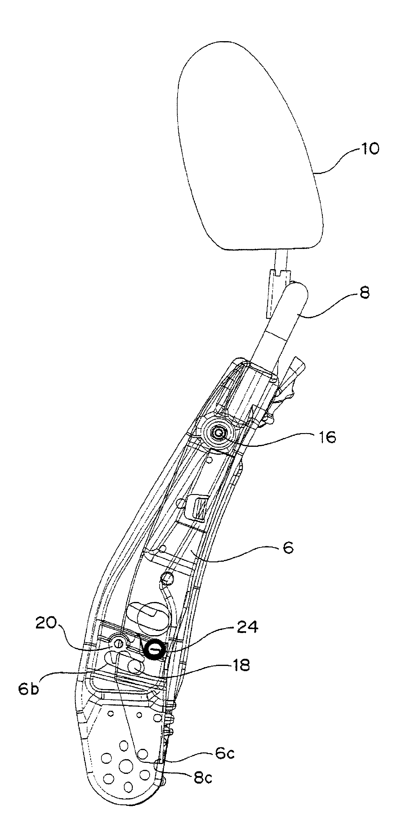
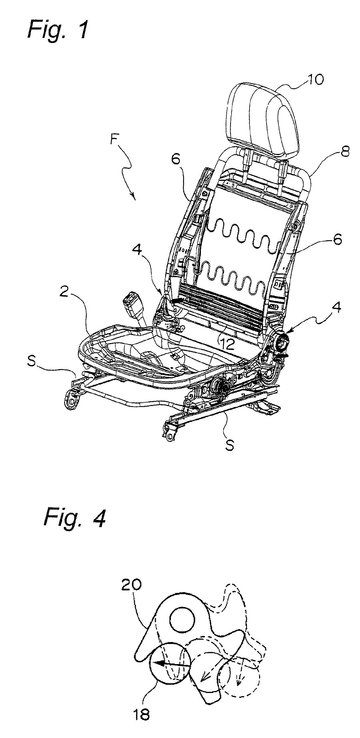
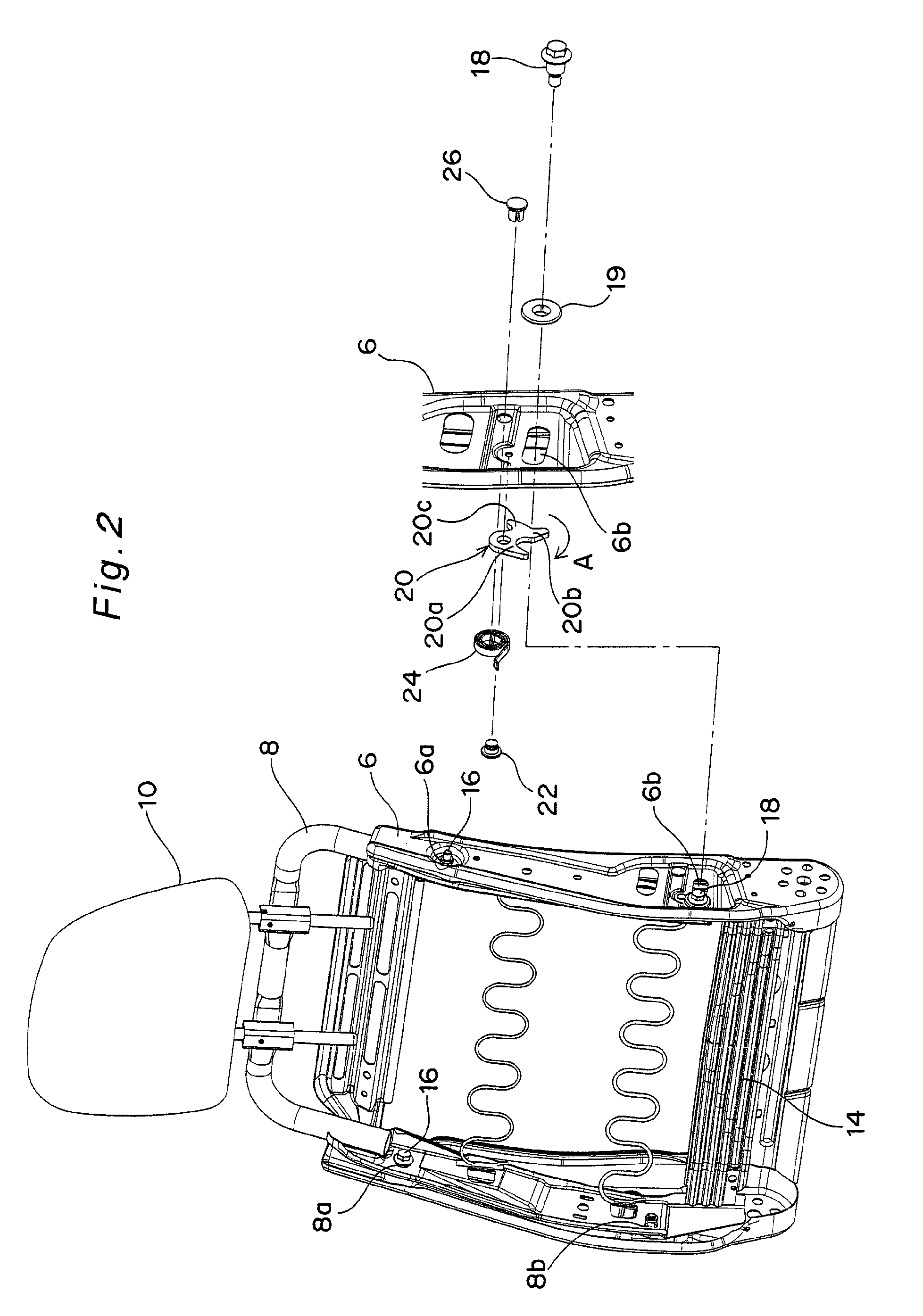
[0044]FIG. 2 depicts a seat back frame of an automobile seat according to a first embodiment of the present invention. As shown in FIG. 2, each side frame 6 has a hinge insertion hole 6a defined in an upper portion thereof and an elongated opening 6b defined in a lower portion thereof in which a swing bolt (described later) is loosely inserted. The elongated opening 6b is formed into an arcuate shape having a center of curvature at the hinge insertion hole 6a.
[0045]On the other hand, the sub-frame 8 is bent in the form of an inverted U and, hence, has a horizontally extending portion and two vertically extending side portions, each of which extends downward from one end of the horizontally extending portion. Each side portion of the sub-frame 8 has a hinge insertion hole 8a at a location confronting the hinge insertion hole 6a in the side frame 6 and a swing bolt insertion hole 8b at a location confronting the elongated opening 6b in the side frame 6. The sub-frame 8 also has a pre...
embodiment 2
[0068]FIGS. 9A and 9B schematically depict an essential portion of an automobile seat according to a second embodiment of the present invention wherein a swinging motion restraint member (swinging motion restraint plate) 20A and a coil spring (tension spring) 30 are used in place of the swinging motion restraint member 20 and the spiral spring 24 (or the coil spring 28) used in the first embodiment.
[0069]More specifically, one end (upper end) of the swinging motion restraint plate 20A is pivotally connected to the side frame 6 above the elongated opening 6b via a pin 32, and one end (lower end) of the coil spring 30 is secured to the other end (lower end) of the swinging motion restraint plate 20A. The other end (upper end) of the coil spring 30 is secured to the side frame 6 above the pin 32, thereby applying a clockwise or counterclockwise moment to the swinging motion restraint plate 20A. It is preferred that the other end of the coil spring 30 be positioned between the hinge bol...
embodiment 3
[0077]FIGS. 10A, 10B and 10C schematically depict a side frame of an automobile seat according to a third embodiment of the present invention wherein an elastic force of a coil spring (tension spring) 34 directly acts on the swing bolt 18 without the provision of the swinging motion restraint member 20 or 20A.
[0078]FIG. 10A depicts an initial state before a user sits on the seat, and FIG. 10B depicts a normal sitting condition in which a load less than the predetermined value is applied to the seat back. FIG. 10C depicts an operating condition of the sub-frame 8 when a load greater than the predetermined value is inputted to the seat back from before in the event of, for example, a rear-end-collision.
[0079]More specifically, one end (lower end) of the coil spring 34 is secured to the swing bolt 18, and the other end (upper end) of the coil spring 34 is secured to the side-frame 6 above the hinge bolt 16. A downward extension of a line that links the hinge bolt 16 and a position wher...
PUM
 Abstract
Description
Claims
Application Information
 - R&D
- Intellectual Property
- Life Sciences
- Materials
- Tech Scout
- Unparalleled Data Quality
- Higher Quality Content
- 60% Fewer Hallucinations
Browse by: Latest US Patents, China's latest patents, Technical Efficacy Thesaurus, Application Domain, Technology Topic, Popular Technical Reports.
© 2025 PatSnap. All rights reserved.Legal|Privacy policy|Modern Slavery Act Transparency Statement|Sitemap|About US| Contact US: help@patsnap.com


