Electric connector, electronic device, and electrically-conductive touch method

a technology of electrical contact and electronic devices, which is applied in the direction of securing/insulating coupling contact members, coupling device connections, fixed connections, etc., can solve the problems of plastic deformation of contact springs, inability to perform incoming processing, and instant loss of electrical touch of contact springs with the electrodes of batteries. , to achieve the effect of reducing occupied space, high contact pressure, and large displacement amoun

Inactive Publication Date: 2012-01-24
ORMON CORP
View PDF6 Cites 5 Cited by
  • Summary
  • Abstract
  • Description
  • Claims
  • Application Information

AI Technical Summary

Benefits of technology

[0009]One or more embodiments of the present invention provides a compact electric connector and a compact electronic device, in which the contact has the high contact pressure and the large displacement amount, and an electrically-conductive touch method in which an occupied space is reduced.
[0011]With this configuration, the contact spring is formed into the double spiral shape to increase a length of the contact spring with respect to the occupied space. When the pressing force of the-other-end electrode acts in the tangential direction of the spiral, the pressing force propagates as a compressive stress or a tensile stress along the extended direction of the contact spring, and the pressing force acts so as to wind or rewind the contact spring. Therefore, the bending stress acts on the whole of the involute portion and revolute portion of the contact spring in the dispersed manner, and the bending stress is not locally concentrated, so that a risk of plastically deforming the contact spring can be eliminated to secure the large contact pressure and displacement amount compared with the dimensions of the contact spring.
[0013]With this configuration, the bend of the arm portion also contributes to the displacement amount of the contact portion. When the contact portion is pushed with respect to the-other-end electrode, the contact portion is moved in the direction orthogonal to the pressing direction of the-other-end electrode to obtain a wiping effect that removes adhesives to the contact portion and the-other-end electrode.
[0015]With this configuration, the buckling of the arm portion can be prevented by the deformation of the escape portion.
[0017]With this configuration, the pressing force of the-other-end electrode can correctly be transmitted in the tangential direction of the spiral to the outside end portion of the revolute portion.

Problems solved by technology

Because occasionally the battery is moved in the chassis of the electronic device, unless a contact pressure of a contact spring is sufficiently increased, there is a possibility of generating temporary blackout in which the electric touch of the contact spring with the electrode of the battery is instantaneously lost.
For example, the mobile telephone is powered off when the temporary blackout is generated in a mobile telephone in a standby state, and incoming processing cannot be performed unless the mobile telephone is powered on again.
When the applied stress exceeds an elastic limit, the contact spring is plastically deformed to generate so-called wear in which a displacement amount or a contact pressure of the contact is lost.
However, wear is easily generated when the electric connector is miniaturized.

Method used


Image

  • Electric connector, electronic device, and electrically-conductive touch method
  • Electric connector, electronic device, and electrically-conductive touch method
  • Electric connector, electronic device, and electrically-conductive touch method

Examples


Embodiment Construction

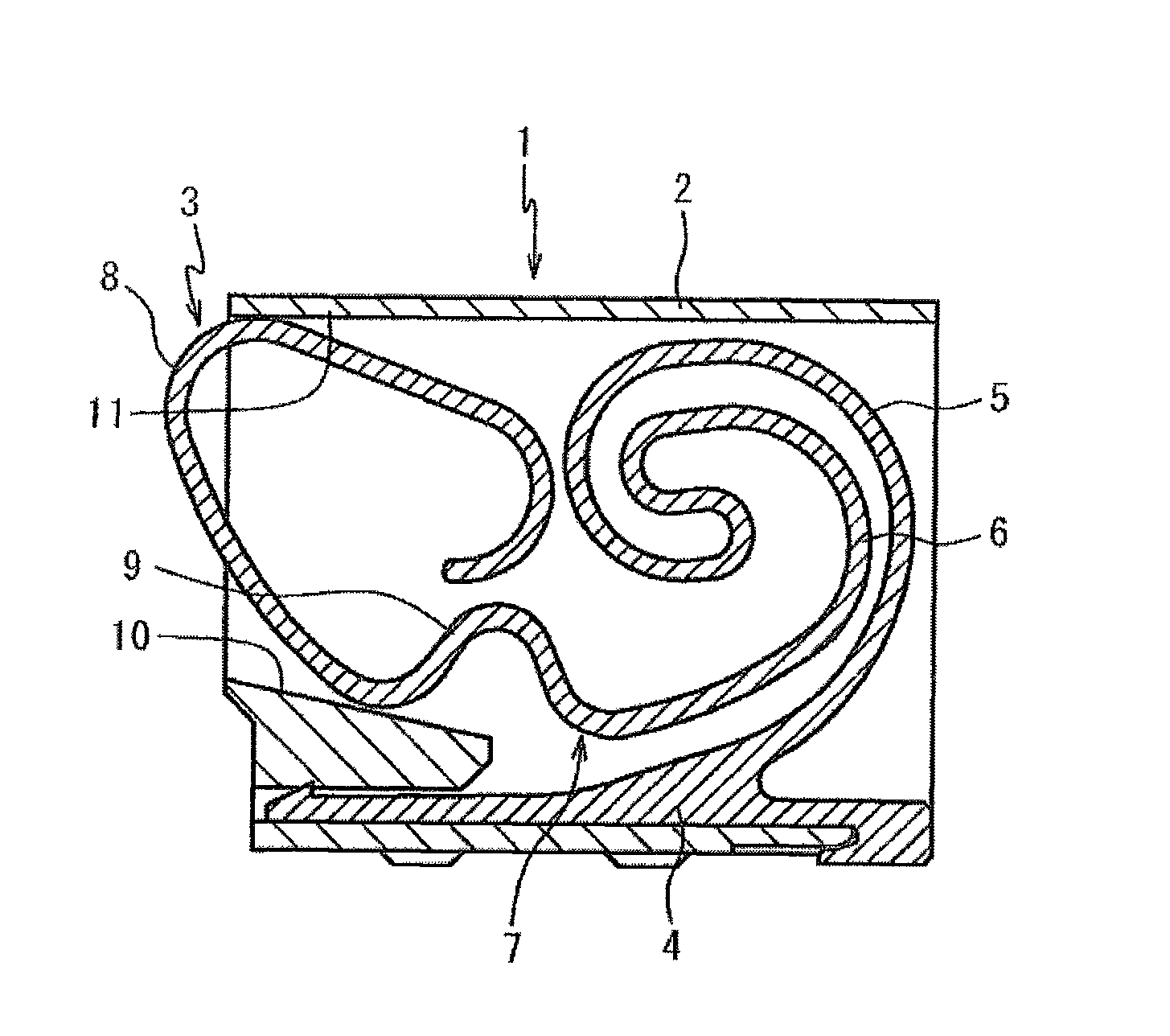
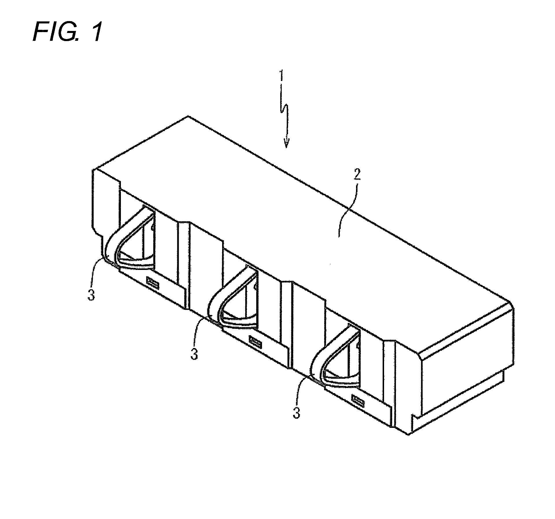
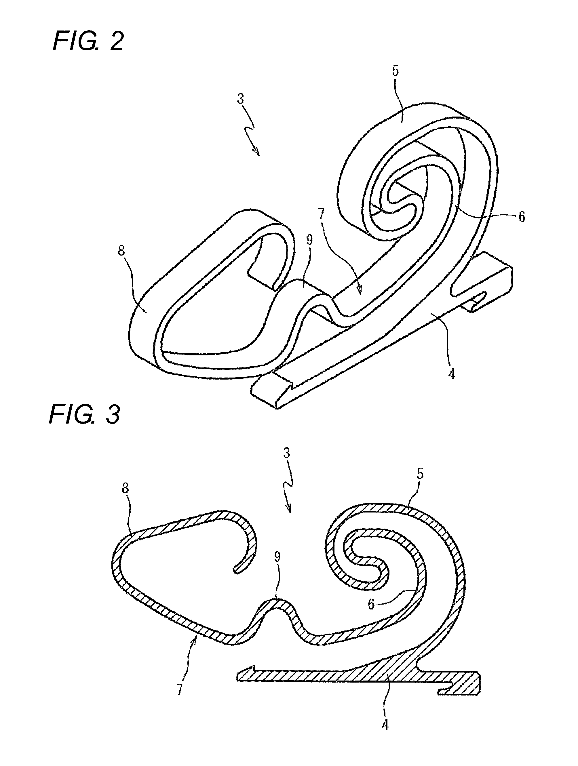
[0032]Hereinafter, embodiments of the present invention will be described with reference to the drawings. In embodiments of the invention, numerous specific details are set forth in order to provide a more thorough understanding of the invention. However, it will be apparent to one of ordinary skill in the art that the invention may be practiced without these specific details. In other instances, well-known features have not been described in detail to avoid obscuring the invention. FIG. 1 is a perspective view of a battery connecting electric connector 1 according to a first embodiment of the present invention. In the electric connector 1, contact springs 3 are inserted in and fixed to three slots formed in a housing 2, respectively.

[0033]In the three contact springs 3, the central contact spring 3 is used as a control contact, and each of the contact springs 3 located on both sides is used as a contact that gets into touch with an electrode (the-other-end electrode) of a battery i...


PUM


Abstract

An electric connector has a contact spring. The contact spring includes a fixed portion that is retained by a housing, an involute portion that is extended from the fixed portion into an inward spiral pattern, a revolute portion that is inverted from the involute portion and extended into an outward spiral pattern along the involute portion, an arm portion that is connected to a tail end portion of the revolute portion, a tangential direction of a portion connected to the revolute portion in the arm portion being aligned with a tangential direction of the tail end portion of the revolute portion, and a contact portion that is provided at a leading end of the arm portion to be projected to an outside of the housing, the contact portion abutting on the-other-end electrode to receive a pressing force in a direction in which the arm portion is substantially extended.

Description

BACKGROUND OF THE INVENTION[0001]1. Technical Field[0002]The present invention relates to an electric connector, an electronic device, and an electrically-conductive touch method.[0003]2. Related Art[0004]Various electric connectors are used in the electronic device. Among others, it is necessary that the electric connector that gets into electrically-conductive touch with an electrode of a battery have a large displacement amount so as to be able to absorb not only a dimension error of the electric connector or a deviation of a mounting position but also a dimension error of a chassis or the battery of the electronic device.[0005]Because occasionally the battery is moved in the chassis of the electronic device, unless a contact pressure of a contact spring is sufficiently increased, there is a possibility of generating temporary blackout in which the electric touch of the contact spring with the electrode of the battery is instantaneously lost. For example, the mobile telephone is ...

Claims


Application Information

Patent Timeline
Patent Type & Authority Patents(United States)
IPC IPC(8): H01R4/48
CPCH01R13/2428H01R12/57
Inventor KOYAMA, JIROTERANISHI, HIROTADA
Owner ORMON CORP
Why Eureka
Try Eureka