
Permeate tube

a technology of permeate tube and membrane, which is applied in the field of permeate tube, can solve the problems of high pressure but is susceptible to fouling of feed channels, and achieve the effect of improving the winding of membrane leaves

Active Publication Date: 2012-01-24
ALFA LAVAL CORP AB
View PDF11 Cites 13 Cited by
  • Summary
  • Abstract
  • Description
  • Claims
  • Application Information

AI Technical Summary

Benefits of technology

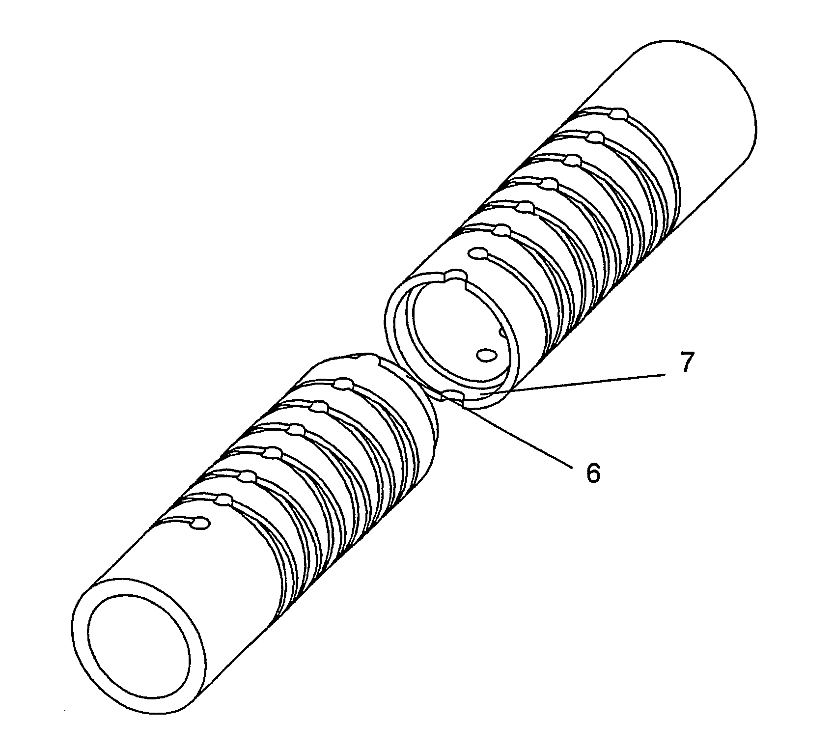
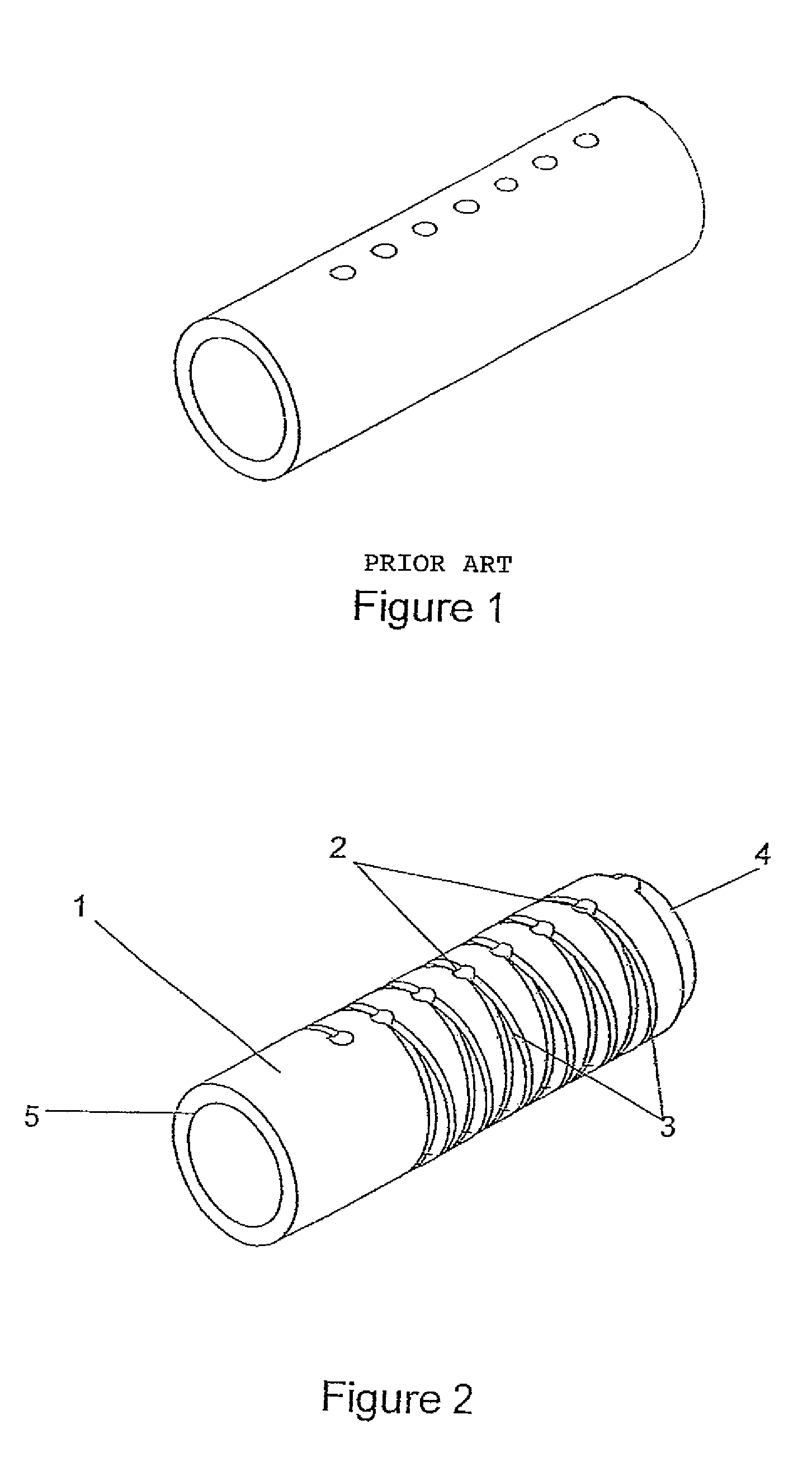
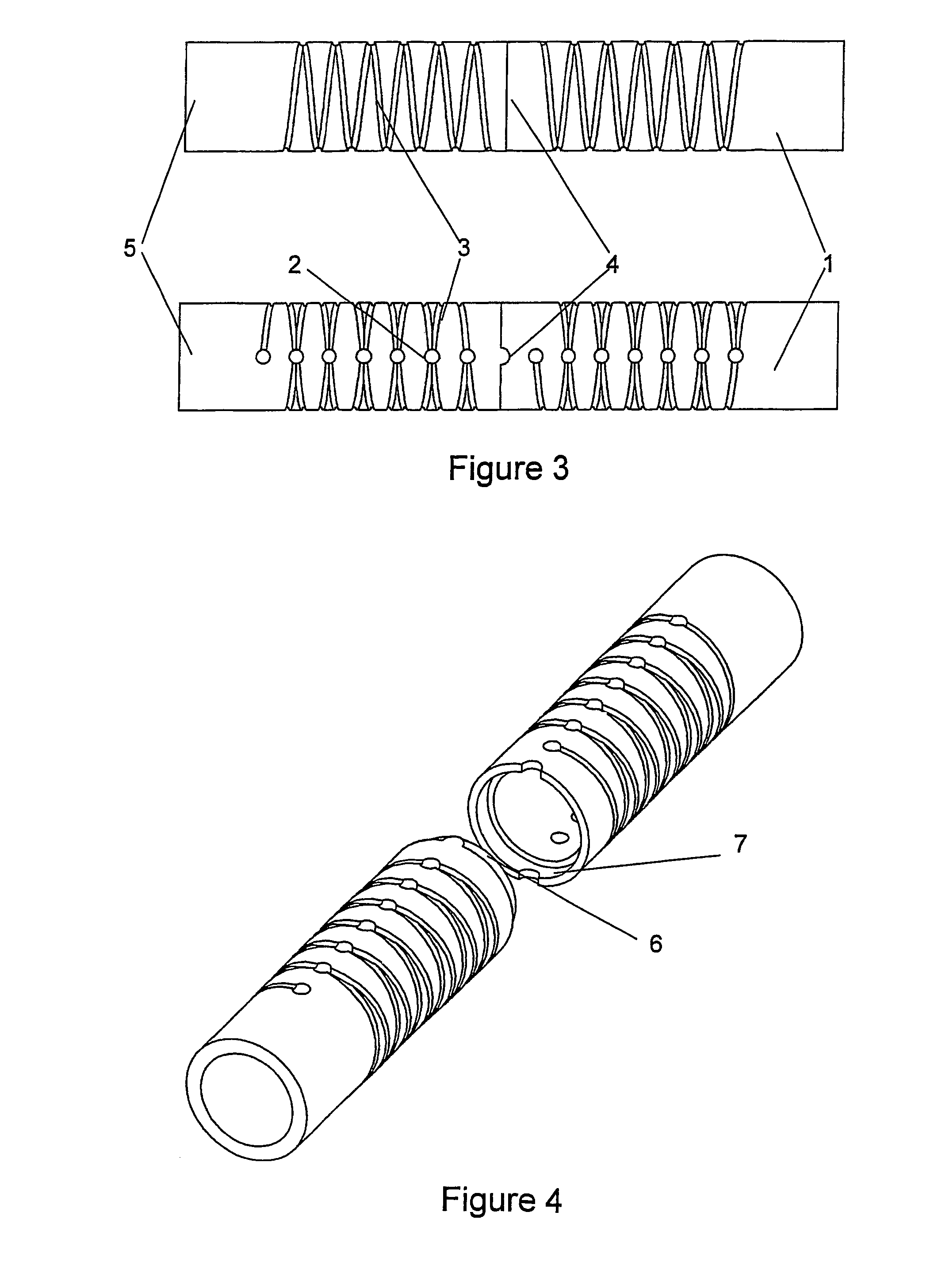
The patent text describes a spiral wound membrane cartridge with a permeate tube that has improved performance by adding a plurality of permeate transfer means and grooves. The grooves create flow channels that transport permeate from the membrane layers or leafs into the interior of the tube. The cross-section of the interior of the tube can be polygonal, such as square, pentagonal, hexagonal, heptagonal, or octagonal, which makes it easier to handle and wind the membrane leafs around the tube. The technical effects of this design include improved membrane performance, reduced fouling of the feed channels, and increased efficiency of the overall cartridge.

Problems solved by technology

This module also can withstand high pressures but is susceptible to fouling of feed channels by suspended particles.

Method used


Image

  • Permeate tube
  • Permeate tube
  • Permeate tube

Examples


example 1

[0041]The permeate tube of the invention was tested against a standard permeate tube of the prior art, the permeate tube of the invention having two rows of holes and two helical grooves connected to the holes, and the standard tube having four rows of holes and no grooves. Around the tested permeate tubes were membrane leaves, permeate transfer sheets, and spacer sheets wounded. The tests were carried out parallel in pressure tubes. The pressures were measured into and out of the tubes by the ends of the tubes, giving an average pressure within the range of from about 2 Bar to about 10 Bar. The temperature was 20° C., the surrounding pressure was 1.0 Bar, and the cross-flow was 30 m3 / h during the test run. The results are summarised in Table 1.

[0042]

TABLE 1Permeate tube ofPermeate tube ofinventionprior artPermeatePermeatePermeatePermeateTimePflowfluxflowfluxminutesBardm3 / hdm3 / (m2 × h)dm3 / hdm3 / (m2 × h)01.93155092145086153.0323001372200131304.0627501642530151405.0530251802860170506.0...

example 2

[0044]The permeate tube of the invention was tested against a standard permeate tube of the prior art, the permeate tube of the invention having two rows of holes having a diameter of 4 mm, and two helical grooves connected to the holes, and the standard tube having four rows of holes having a diameter of 2.5 mm and no grooves. Around the tested permeate tubes were membrane leaves, permeate transfer sheets, and spacer sheets wounded. The tests were carried out parallel in pressure tubes where the inlet and outlet pressures were measured. In all the tests the inlet pressures were about 2.7 Bar and the outlet pressures were about 1.7 Bar. The tests were carried out within a temperature range of from 20 to 50° C. at a surrounding pressure of about 1.0 Bar. The cross-flow were about 35 m3 / h during the test runs. The test medias were 1) deionised water and 2) thin milk having refractive index equal to 4.6. The results are summarised in Table 2.

[0045]

TABLE 2Permeate tube ofPermeate tube o...


PUM

PropertyMeasurementUnit
depthaaaaaaaaaa
temperatureaaaaaaaaaa
depthaaaaaaaaaa

Abstract

A permeate tube for spiral wound membrane comprising at least one tubular unit, which unit has spaced along its length a plurality of permeate transfer means, and one or more external grooves forming flow channels connecting the permeate transfer means. The present invention relates further to a process for treating a material having a viscosity less than 50 cP by the use of a spiral wound membrane comprising a permeate tube having at least one tubular unit, which unit has spaced along its length a plurality of permeate transfer means, and one or more external grooves forming flow channels connecting the permeate transfer means, around the permeate tube are one or more permeate transfer leaves, one or more membrane leaves and one or more space leaves wound. The present invention relates also to a process of operating a spiral wound membrane. The present invention relates further to uses of the spiral wound membrane.

Description

[0001]Present invention relates to a permeate collection tube for use in a spiral wound membrane, a spiral wound membrane, a process of operating a spiral wound membrane, a process for treating materials by the use of a spiral wound membrane and uses of the spiral wound membrane.BACKGROUND OF INVENTION[0002]Spiral wound membrane have often been produced by winding a membrane leaf or leaves, a permeate transfer sheet, and a spacer sheet around a perforated central collection tube.[0003]A great number of spiral wound membranes are known from literature for example EP 0347174, U.S. Pat. No. 4,735,717 and U.S. Pat. No. 3,966,616, which documents disclose spiral wound membrane cartridges having collection tubes around which permeate transfer leaves, membrane leaves and space leaves are wound. U.S. Pat. No. 4,476,022 discloses a serrated product tube having perforations. A hollow tubular collection member provided with a plurality of randomly dispersed slots or apertures on its outer circ...

Claims


Application Information

Patent Timeline
Patent Type & Authority Patents(United States)
IPC IPC(8): B01D35/00B01D69/00B01D61/00
CPCB01D63/10B01D65/00Y10T428/13Y10T428/139Y02A20/131B01D63/107
Inventor LARSEN, KNUD VERNER
Owner ALFA LAVAL CORP AB
Learn More