Method for LED-module assembly

a technology of led modules and led-supporting electronics, which is applied in the direction of lighting and heating apparatus, semiconductor/solid-state device testing/measurement, instruments, etc., can solve the problems of high cost due to high complexity, particularly difficult to keep leds and led-supporting electronics in water/air tight environments, and difficult to meet the requirements of high-luminance light fixtures using led modules as light sources

Active Publication Date: 2012-01-24
IDEAL IND LIGHTING LLC
View PDF11 Cites 65 Cited by
  • Summary
  • Abstract
  • Description
  • Claims
  • Application Information

AI Technical Summary

Problems solved by technology

High-luminance light fixtures using LED modules as light source present particularly challenging problems.
High costs due to high complexity becomes a particularly difficult problem when high luminance, reliability, and durability are essential to product success.
Keeping LEDs and LED-supporting electronics in a water / air-tight environment may also be problematic, particularly when, as with roadway lights and the like, the light fixtures are constantly exposed to the elements.
Use of a plurality of LED modules presents further challenges.
Yet another cost-related challenge is the problem of achieving a high level of adaptability in order to meet a wide variety of different luminance requirements.
That is, providing a fixture which can be adapted to give significantly greater or lesser amounts of luminance as deemed appropriate for particular applications is a difficult problem.
Dealing with heat dissipation requirements is still another problem area for high-luminance LED light fixtures.
Heat dissipation is difficult in part because high-luminance LED light fixtures typically have a great many LEDs and several LED modules.
Complex structures for module mounting and heat dissipation have sometimes been deemed necessary, and all of this adds to complexity and cost.

Method used


Image

  • Method for LED-module assembly
  • Method for LED-module assembly
  • Method for LED-module assembly

Examples


Embodiment Construction

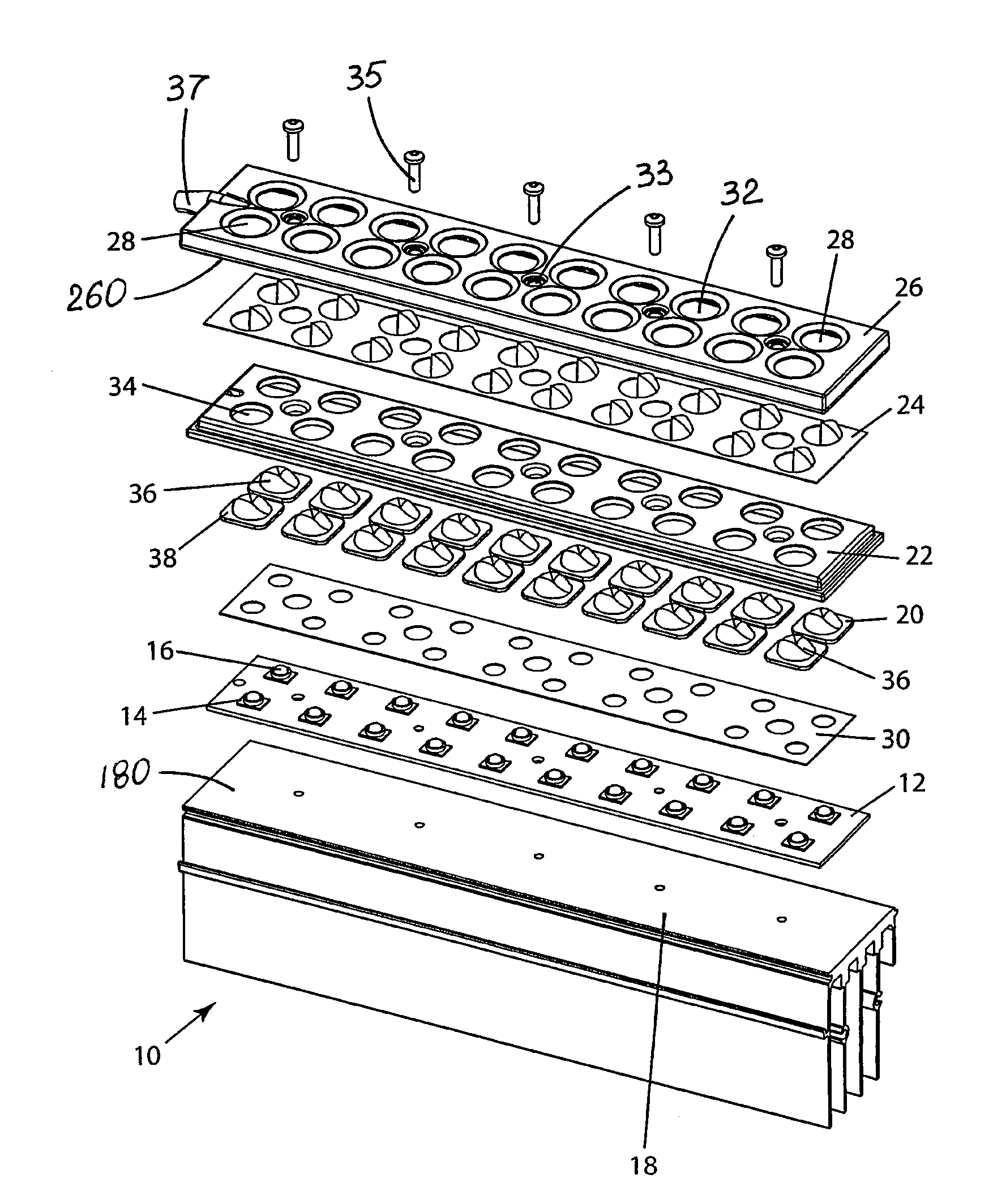
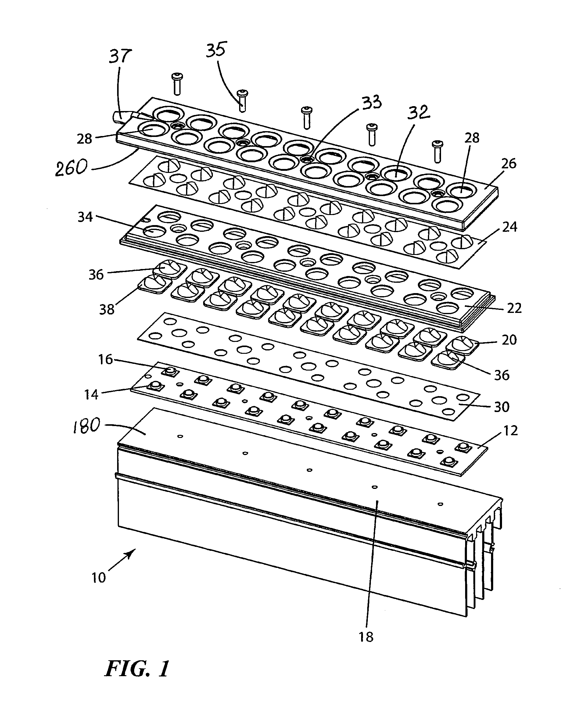
[0031]FIGS. 1, 3 and 4 illustrate an LED module 10 which includes a mounting board 12 with a plurality of LED emitters 14 thereon. Illustrated LED emitters 14 include primary lenses 16. A secondary LED lens 20 is positioned over each emitter 13. Mounting board 12 is connected to a base portion which is shown as a heat sink 18. One or more LED modules 10 may be used as light sources in various LED lighting fixtures. LED module 10 includes a sealing device shown in the form of a resilient member 22 against which LED lenses 20 are positioned. Resilient member 22 yieldingly constrains secondary lenses 20 and accommodates the movement of secondary lenses 20 caused by thermal expansion during LED operation. Such expansion is mostly caused by primary lenses 16 in the embodiment shown in FIGS. 1 and 4.

[0032]FIGS. 1 and 4 show resilient member 22 in the form of a gasket layer between a cover 26 and mounting board 12. Gasket 22 has a plurality of gasket apertures 34 and is preferably made fro...


PUM


Abstract

A method for LED-module assembly comprising the steps of providing a base portion with a base inner surface and a cover with a cover inner surface which together define a module interior, the cover having at least one opening therethrough; putting a sealing member into the module interior; positioning an LED lens into the cover opening; aligning an LED emitter and the LED lens within the module interior; sealing the module interior by securing the base portion with respect to the cover. The LED emitter is powered for imaging of the LED module to test light-output characteristics. A specific type of the LED lens is selected and its type and orientation are verified. The step of vacuum testing checks for water-air / tightness of the sealing of LED-module interior. A central database provides assembly and testing parameters to automated tool(s) performing each particular step. Each LED module includes a unique machine-identifiable module-marking with which the data related to each individual LED module is associated and stored in the central database.

Description

RELATED APPLICATION[0001]This application is based in part on U.S. Provisional Application Ser. No. 61 / 056,412, filed May 27, 2008, the contents of which are incorporated herein by reference.FIELD OF THE INVENTION[0002]This invention relates to lighting fixtures and, more particularly, to methods of assembling lighting fixtures using LED emitters.BACKGROUND OF THE INVENTION[0003]In recent years, the use of light-emitting diodes (LEDs) for various common lighting purposes has increased, and this trend has accelerated as advances have been made in LEDs and in LED-array bearing devices, often referred to as “LED modules.” Indeed, lighting applications which have been served by fixtures using high-intensity discharge (HID) lamps and other light sources are now increasingly beginning to be served by LED modules. Such lighting applications include, among a good many others, roadway lighting, parking lot lighting and factory lighting. Creative work continues on development of lighting fixt...

Claims


Application Information

Patent Timeline
Patent Type & Authority Patents(United States)
IPC IPC(8): G01R31/26
CPCF21V5/04F21V31/005F21W2131/103F21Y2101/02F21Y2115/10
Inventor GUILLIEN, WAYNESIEBERS, SCOTKAPELLUSCH, JOELWILCOX, KURT S.
Owner IDEAL IND LIGHTING LLC
Why Eureka
Try Eureka