Ammunition firing device incorporating a firing pin

a firing device and firing pin technology, applied in the direction of ammunition fuzes, detonators, weapons components, etc., can solve the problems of complex device structure, no longer factor in the spin rate of the projectile, and complex structure of the device, so as to achieve easy transposition and reduce the effect of dimensions

Active Publication Date: 2012-01-31
NEXTER MUNITIONS
View PDF10 Cites 7 Cited by
  • Summary
  • Abstract
  • Description
  • Claims
  • Application Information

AI Technical Summary

Benefits of technology

[0029]The device according to the invention is easily transposable to the manufacture of a device of very reduced dimensions and in particular to a device made using MEMS technology.

Problems solved by technology

Such architecture is, however, complicated and necessitates the manufacture of many mechanical parts incorporating precise machining.
This device is complicated in structure.
This solution, which is particularly costly with regard to machining and assembly, means that the spin rate of the projectile is no longer a factor.
It is, however, not very reliable, the balls only remaining in the locking position because of the single action of the counterweight return spring.
However, to date no firing device for ammunition is known with a mechanical firing pin that implements MEMS technology.
One of the reasons explaining this absence of solution is the impossibility of producing tensed-state springs using MEMS technology.

Method used


Image

  • Ammunition firing device incorporating a firing pin
  • Ammunition firing device incorporating a firing pin
  • Ammunition firing device incorporating a firing pin

Examples


first embodiment

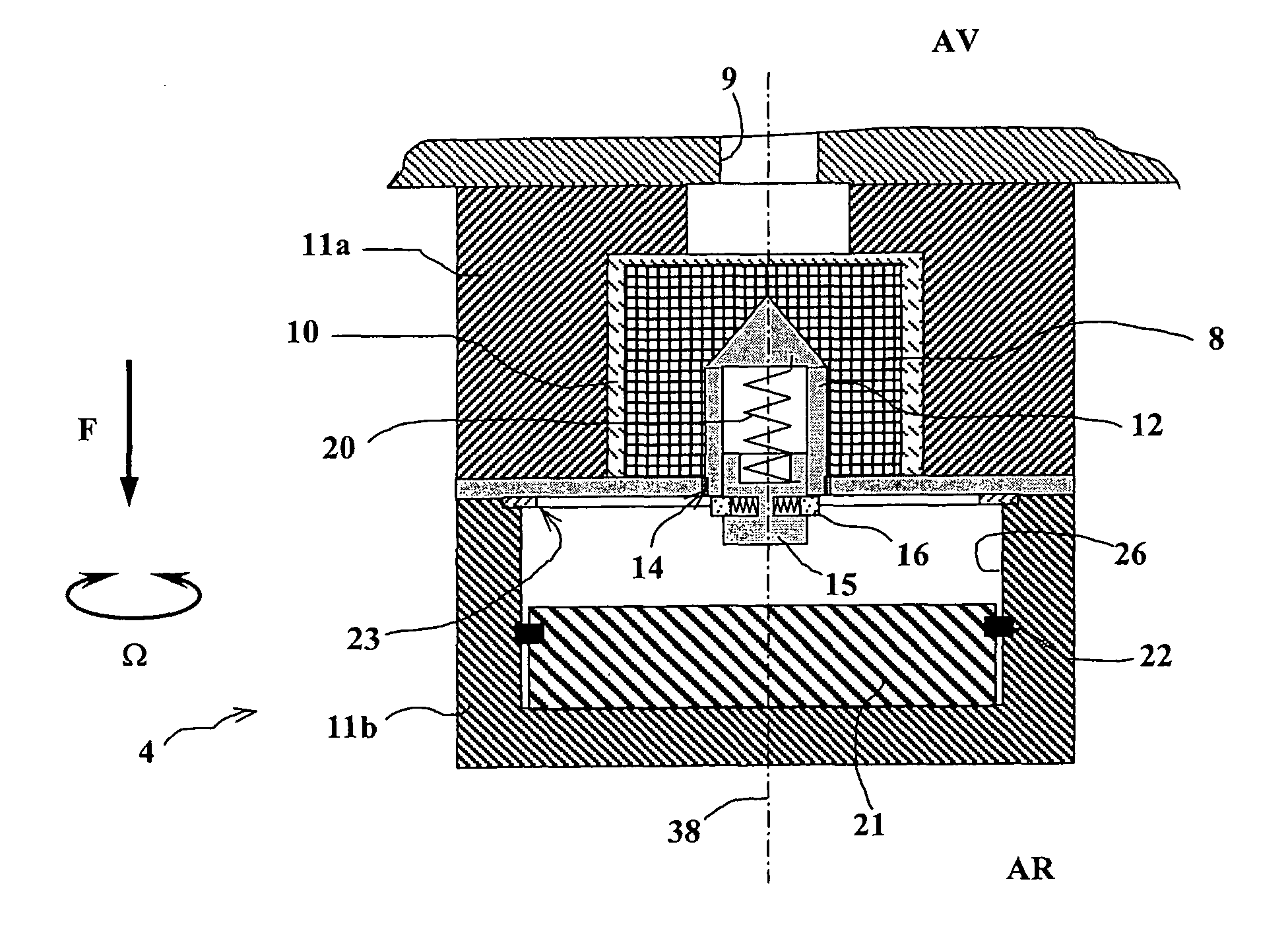
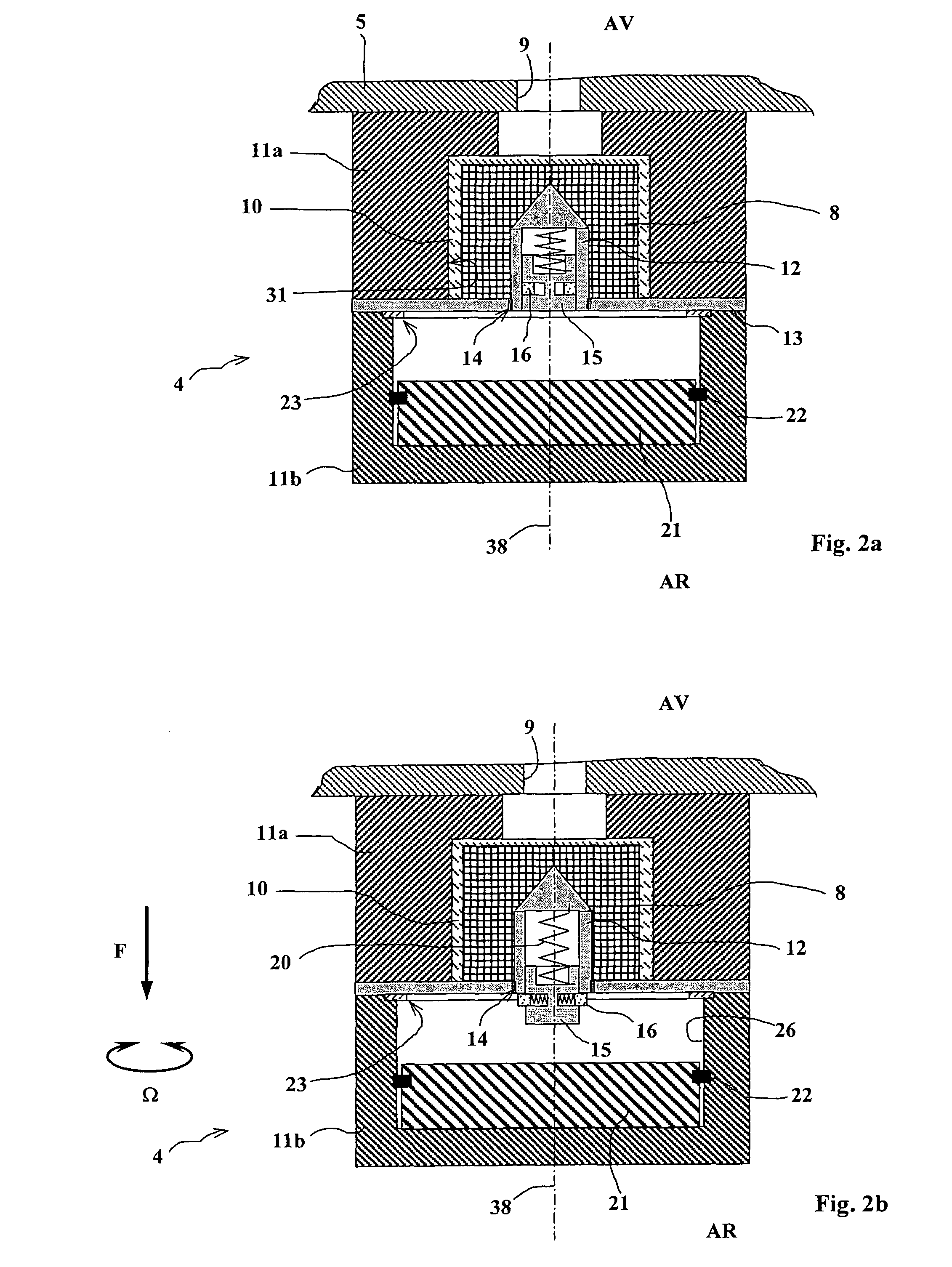
[0051]FIGS. 2a to 2c show a firing device according to the invention.

[0052]This device incorporates a percussion-sensitive pyrotechnic composition 8 arranged in a cup 10 positioned in a cavity 31 of a front part 11a of a body of the device 4. A percussion tip 12 is fixed in the cup 10 and is in contact with the pyrotechnic composition 8. This tip is integral with a partition 13 that is positioned between the rear part 11b and front part 11a of the device's body. The partition 13 also enables the cavity 31 and the cup 10 enclosing the composition 8 to be closed.

[0053]The front 11a and rear 11b parts of the body are linked to one another by means not shown, for example by a threaded ring. A washer 23 is positioned between these two parts.

[0054]The tip 12 is made integral with the partition 13 by shearable linking means 14, for example threading.

[0055]The tip 12 has an inner housing inside which a rod 15 is mounted sliding.

[0056]The rod 15 may slide between a retracted position (FIG. 2...

second embodiment

[0078]FIGS. 3a, 3b and 3c describe a second embodiment that does not differ from the previous one except in the structure of the hammer 21 that is implemented.

[0079]According to this embodiment, the hammer 21 incorporates radial drill holes 24 in which balls 25 are positioned. The hammer 21 is guided in its housing 26 by a front seat 21a. This guidance is completed by the sliding of a rear extension 21b of lesser diameter in a hole 27 in the rear part 11b of the device body.

[0080]A compression spring 28 is mounted around the rear extension 21b. This spring is positioned between the bottom of the housing 26 and the hammer 21.

[0081]The Figures also show that the rear part of the housing 26 has a conical profile 26a whose tapering is oriented with the summit of the cone pointing to the fore AV of the ammunition. The axial acceleration F of the projectile during firing causes the hammer 21 to recoil and the spring 28 to be compressed. The balls 25 are radially distanced through the acti...


PUM


Abstract

An ammunition firing device incorporating a firing pin intended to impact a pyrotechnic composition to activate its ignition, wherein said firing pin incorporates a rod that slides when said ammunition is fired through the effect of the firing acceleration from a starting position to a deployed position, able to be locked in said deployed position, said rod being integral with a percussion tip occupying a fixed position in contact with said pyrotechnic composition, said rod being located fully inside said tip in said starting position and protruding from said tip in its deployed position, said device further incorporating a hammer to strike said rod during the impact of said ammunition on a target to cause the ignition of said composition.

Description

BACKGROUND OF THE INVENTION[0001]1. Field of the Invention[0002]The technical scope of the invention is that of ammunition firing devices using a mechanical firing pin that impacts a pyrotechnic composition.[0003]2. Description of the Related Art[0004]Classically, firing devices incorporate a firing pin projected via inertia onto the pyrotechnic composition after a certain number of safety barriers have been raised. This firing pin is also very often projected by a spring, so as to ensure a self-destruct function (when, for example, there is no impact on a target).[0005]Patent FR-2689972 thus discloses a firing device for a medium caliber projectile (caliber of between 20 mm and 50 mm). This device comprises a firing pin that can be pushed towards a primer by means of a spring.[0006]So as to avoid any risk of inadvertent percussion during the storage or transport phases, the primer is integral with an arming rotor that enables it to be kept at a distance from the firing pin before f...

Claims


Application Information

Patent Timeline
Patent Type & Authority Patents(United States)
IPC IPC(8): F42C15/24
CPCF42C1/04F42C15/24
Inventor LAFONT, RENAUDMAGNAN, PIERRE
Owner NEXTER MUNITIONS
Why Eureka
Try Eureka