Adjustable and rotary rudder bar for a rotary wing aircraft
a rotary wing aircraft and rudder bar technology, which is applied in the direction of aircraft control, aircraft components, aircraft without power amplifier, etc., can solve the problems of complex installation of rudder bars on rotary wing aircraft, imposed constraints on aircraft architecture, and additional constraints, and achieves easy transposal
- Summary
- Abstract
- Description
- Claims
- Application Information
AI Technical Summary
Benefits of technology
Problems solved by technology
Method used
Image
Examples
first embodiment
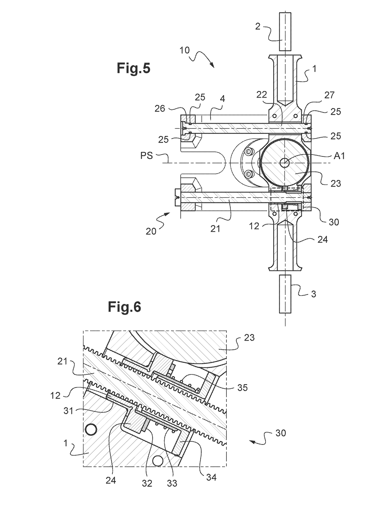
[0106]The slider device 20 in the rudder bar 10 is shown in detail in FIG. 5. The slider device 20 comprises a lead screw 21, a guide bar 22 substantially parallel to the lead screw 21, a toothed wheel 23, a pinion 24, and a nut 12.
[0107]The lead screw 21 is secured to the main body 4 and is thus stationary relative to the main body 4. The guide bar 22 is connected to the main body 4 via a pivot connection formed more precisely by a pivot connection 26 at one end of the guide bar 22 and by a sliding pivot connection 27 at the other end of the guide bar 22. The guide bar 22 is connected to the pedal bar 1 via a sliding pivot connection 29.
[0108]The toothed wheel 23 and the pinion 24 are connected to the pedal bar 1 via respective pivot connections. The toothed wheel 23 is constituted by a gear having helical teeth meshing with the pinion 24. The nut 12 is secured to the pinion 24 and thus constrained to rotate with the pinion 24. The nut 12 is connected to the pedal bar 1 by a pivot ...
second embodiment
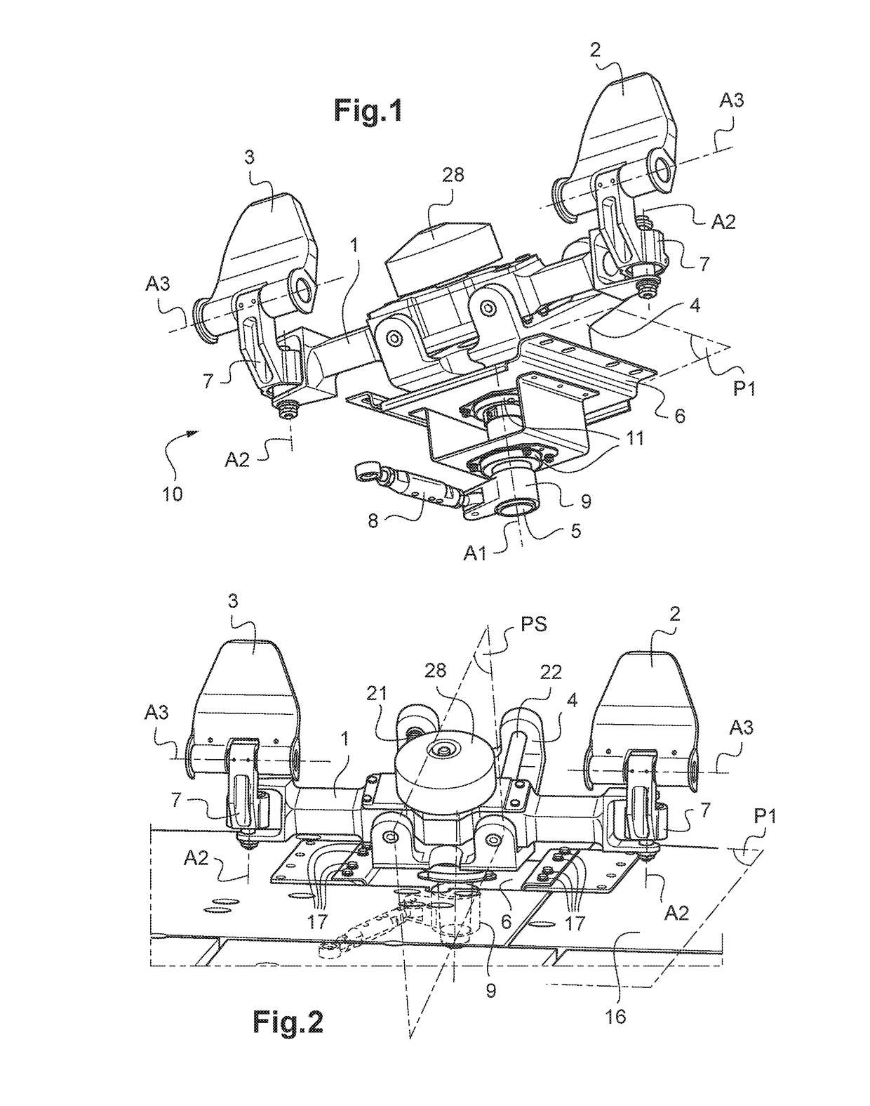
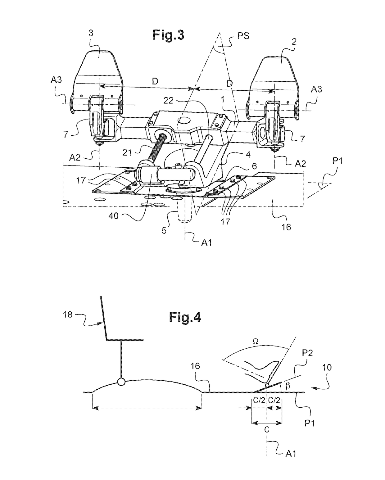
[0124]In the rudder bar 10 shown in FIG. 3, the slider device 20 includes an electric motor 40 for driving the lead screw 21 in turning, possibly via rotary speed reduction gearing incorporating in the electric motor 40. In this embodiment, the nut 12 is secured to the pedal bar 1 and the lead screw 21 is connected to the main body 4 via a pivot connection.
[0125]In this second embodiment, the rudder bar 10 does not have a connecting rod 8 or a crank 9. The ball bearings 11 include position sensors accurately defining the angular position of the shaft 5 about the first axis A1. In this second embodiment, the rudder bar 10 is for use with electrical flight controls of the aircraft. The angular position of the shaft 5 defined by these sensors then enables yaw movements of the aircraft to be piloted via an electrical control system.
third embodiment
[0126]the rudder bar 10 is shown in FIG. 8. The rudder bar 10 has two servo-controls 45. Each servo-control 45 is connected to a respective pedal 2, 3, with each pedal 2, 3 being movable in turning about the third axis A3. Each servo-control 45 is also connected to a connection support 7 by a pivot connection. Each servo-control 45 is connected to a braking system for braking at least one wheel of landing gear of the aircraft. As a result, action of the pilot's foot on a pedal 2, 3 about the third axis A3 acts on a servo-control 45 for the purpose of controlling braking of the aircraft on the ground by means of wheels of its landing gear.
PUM
 Abstract
Description
Claims
Application Information
 - R&D
- Intellectual Property
- Life Sciences
- Materials
- Tech Scout
- Unparalleled Data Quality
- Higher Quality Content
- 60% Fewer Hallucinations
Browse by: Latest US Patents, China's latest patents, Technical Efficacy Thesaurus, Application Domain, Technology Topic, Popular Technical Reports.
© 2025 PatSnap. All rights reserved.Legal|Privacy policy|Modern Slavery Act Transparency Statement|Sitemap|About US| Contact US: help@patsnap.com


