Positioning system and positioning method

a positioning system and receiver technology, applied in the field of positioning system and positioning method for estimating the position of a receiver, can solve the problems of ue-based agps positioning method, which is used in satellite radio beaconing, measurement devices, instruments, etc., and achieves the effect of less tim

Inactive Publication Date: 2012-01-31
POLARIS WIRELESS +1
View PDF14 Cites 56 Cited by
  • Summary
  • Abstract
  • Description
  • Claims
  • Application Information

AI Technical Summary

Benefits of technology

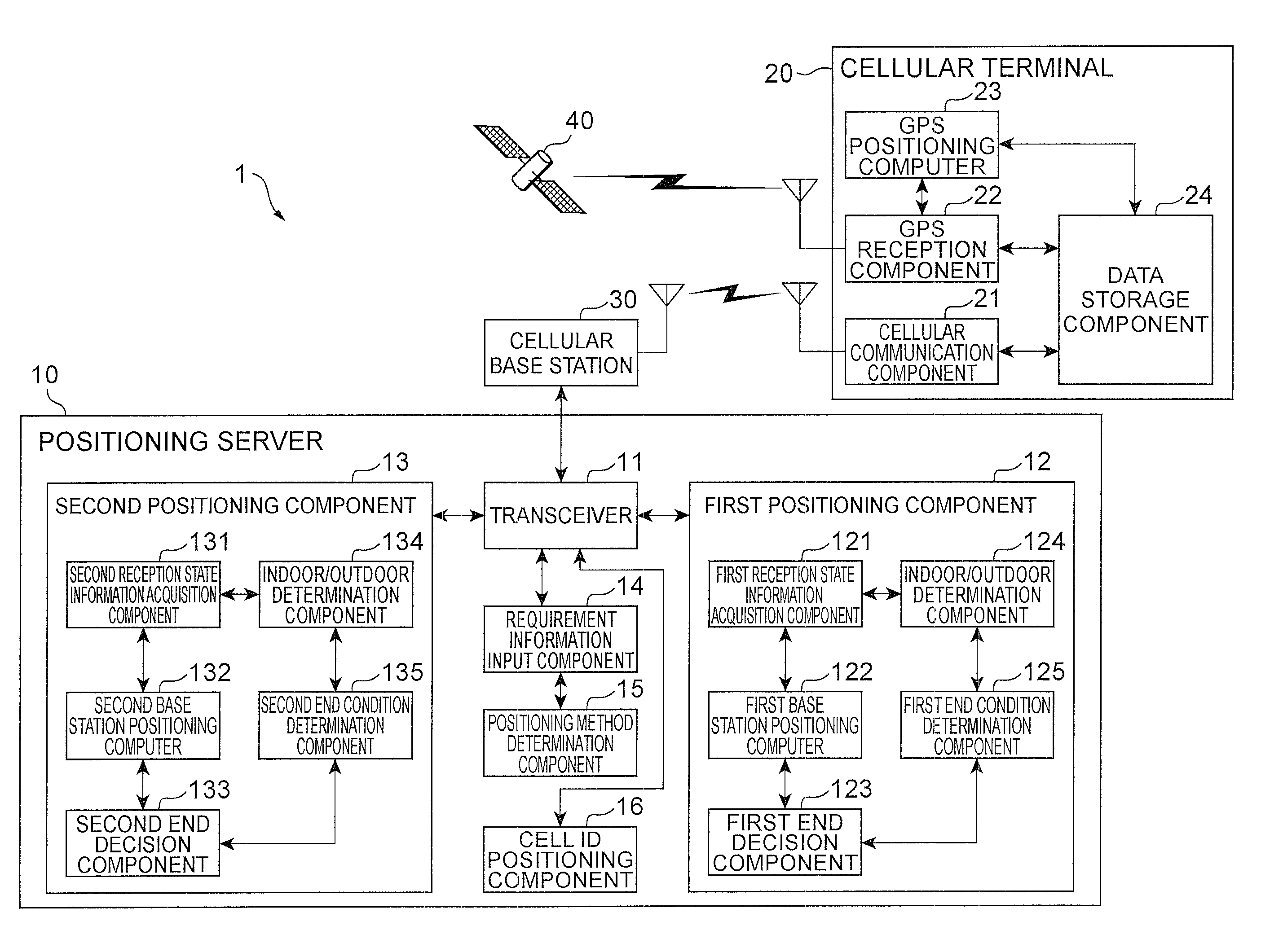
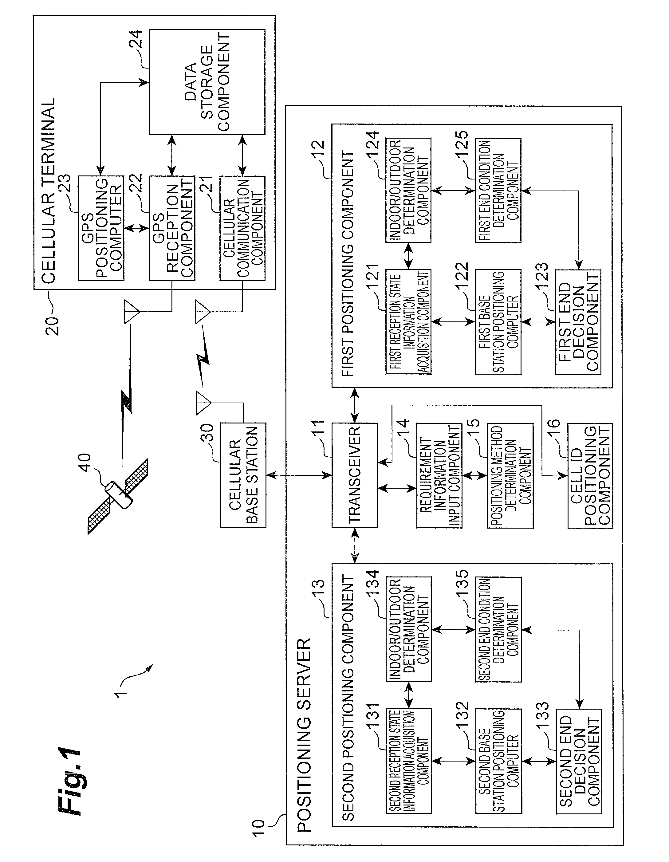
[0012]Therefore, control can be performed so that even if the receiver does not perform GPS positioning, if the approximate position has sufficient precision, or if GPS positioning is difficult to perform, GPS positioning is not executed, and otherwise GPS positioning is executed. Also, with the above positioning system, whether or not GPS positioning is performed can be controlled without actually performing GPS positioning, which takes a long time to decide if it has been executed. Specifically, with the positioning system pertaining to the present invention, a positioning result corresponding to the state of the receiver can be obtained in less time.
[0013]As discussed above, with the positioning system pertaining to the present invention, a positioning method corresponding to requirement information is decided and executed from among two positioning methods each having a different positioning time and positioning precision, so positioning can be performed at the proper positioning time and positioning precision according to a requirement with respect to positioning.
[0016]Preferably, the first reception state information acquisition means acquires strength information indicating the reception strength corresponding to an emission source of the radio wave as the reception state information, and the first position estimation means estimates the position of the receiver by storing in advance information indicating the relation between the position and reception strength of the radio wave corresponding to an emission source of the radio wave, and by comparing the strength information acquired by the first reception state information acquisition means with the information stored in advance. With this constitution, the position of the receiver can be reliably and favorably estimated on the basis of the radio wave received by the wireless communication function of the receiver.
[0018]Preferably, the positioning system further comprises emission source positioning means for acquiring information indicating the size of a communication area of an emission source of the radio wave received by the receiver, estimating the position of the receiver on the basis of the size of the communication area, and deciding whether or not to cause the first positioning means or second positioning means to execute the estimation of the position of the receiver. With this constitution, the positioning result can be easily acquired according to the environment in which the receiver is placed.
[0020]Preferably, the reception state information acquisition means acquires strength information indicating the reception strength corresponding to an emission source of the radio wave as the reception state information, and the estimation of the approximate position by the approximate position estimation means and the estimation of the position of the receiver which uses the reception state information and the execution of which is controlled by the positioning control means, are carried out by a method in which the position of the receiver is estimated by storing in advance information indicating the relation between the position and reception strength of the radio wave corresponding to the emission source of the radio wave, and by comparing the strength information acquired by the reception state information acquisition means with the information stored in advance. With this constitution, the position of the receiver can be reliably and favorably estimated on the basis of the radio wave received by the wireless communication function of the receiver.

Problems solved by technology

With conventional methods, however, whether or not positioning by GPS was successful could not be decided without actually commencing the positioning.
Also, GPS positioning that entailed the above-mentioned decision took a long time.
And a UE-based AGPS positioning method, in which computation is performed by the receiver, took an especially long time.
For example, indoors where a signal cannot be received from a GPS satellite, after GPS positioning has proven impossible, the system switched to a different type of positioning such as base station positioning, so the overall positioning took a long time.
In this case, the positioning precision is poor for how long the positioning takes.
Also, in cities and the like, even outdoors the effect of multipulses can prevent good GPS positioning precision from being attained.

Method used


Image

  • Positioning system and positioning method
  • Positioning system and positioning method
  • Positioning system and positioning method

Examples


first modification example

[0180]The functional configuration of the indoor / outdoor determination component 124, 134 in the first modification example is the same as the functional configuration shown in FIG. 4 and discussed above, but the indoor / outdoor determination processing (indoor / outdoor determination method) is expressed by the flowchart in FIG. 14. Specifically, in the indoor / outdoor determination processing in the first modification example, first the reception component 52 of the indoor / outdoor determination component 124, 134 receives from the cellular terminal 20 MR including emission source identification information about the received signal (S21 in FIG. 14), and the specification component 53 counts the number of pieces of emission source identification information included in the received MR, and thereby specifies the emission source number N of the received signal (S22). Next, the possibility determination component 54 determines whether or not the emission source number N is equal to or gre...

second modification example

[0186]As shown in FIG. 15, the indoor / outdoor determination component 124, 134 in the second modification example comprises the same determination database 51, reception component 52, and specification component 53 as in the above embodiment, as well as a setting component 57 and a determination controller 58. Of these, the setting component 57 extracts from the determination database 51 combined information including all of the emission source identification information included in the MR, and sets the lowest value of the number of emission sources included in the extracted combined information as the minimum emission source number Q. The determination controller 58 performs indoor / outdoor determination by the procedure discussed below, on the basis of the emission source number N, the minimum emission source number Q, and the minimum emission source number P at which indoor / outdoor determination is possible.

[0187]The indoor / outdoor determination processing (indoor / outdoor determin...


PUM


Abstract

It is an object of the present invention to perform positioning at the proper positioning time and positioning precision in response to a requirement with respect to positioning. A positioning server 10 comprises a first positioning component 12 that performs positioning of a cellular terminal 20 by a hybrid algorithm 1, in which indoor / outdoor determination is performed on the basis of reception state information indicating the reception state at the cellular terminal 20, and in which an end condition is determined on the basis of the result of the indoor / outdoor determination; and a second positioning component 13 that performs positioning of the cellular terminal 20 by a hybrid algorithm 2, in which the approximate position of the cellular terminal 20 is calculated on the basis of reception state information indicating the reception state at the cellular terminal 20, and in which whether or not to end the positioning of the cellular terminal 20 is decided on the basis of the precision of the approximated position.

Description

BACKGROUND OF THE INVENTION[0001]1. Field of the Invention[0002]The present invention relates to a positioning system and a positioning method for estimating the position of a receiver.[0003]2. Related Background Art[0004]There has been proposed in the past a technique for estimating the position of a cellular terminal (mobile communication terminal) or other such receiver on the basis of the reception strength (reception level) of the radio wave received by the receiver. Japanese Patent Application No. H7-231473, which is a Japanese laid-open patent application, discusses a technique for estimating the position of a receiver by taking information indicating the relation between the reception strength of a radio wave received from a specific base station and the position at which this radio wave was received, storing this information in a database, and using this database to match with reception strength.[0005]Also known in the past was a technique for using a GPS (global positionin...

Claims


Application Information

Patent Timeline
Patent Type & Authority Patents(United States)
IPC IPC(8): G01S19/48G01S19/46
CPCG01S19/48G01S5/0252G01S5/02521G01S5/015
Inventor BHATTACHARYA, TARUN KUMAREL-SALLABI, HASSAN MOHAMEDGORDON, SCOT DOUGLASODA, YASUHIROSHEN, JIYUN
Owner POLARIS WIRELESS
Why Eureka
Try Eureka