Latching structure of mobile electronic device

a technology of mobile electronic devices and latching structures, which is applied in the direction of carpet fasteners, electrical apparatus casings/cabinets/drawers, instruments, etc., can solve the problems of inconvenient user opening of the display from the base the lock position of the latching structure of the mobile electronic device is quite limited, and the conventional latching structure has to occupy a large volume. , to achieve the effect of convenient opening of the display, convenient storag

Inactive Publication Date: 2012-02-07
COMPAL ELECTRONICS INC
View PDF17 Cites 20 Cited by
  • Summary
  • Abstract
  • Description
  • Claims
  • Application Information

AI Technical Summary

Benefits of technology

[0005]One objective of the present invention is to provide a latching structure of a mobile electronic device to conveniently release the display from the base of the mobile electronic device with a button.
[0006]Another objective of the present invention is to provide a latching structure of a mobile electronic device to connect the button module and the hook module thereof with a linking rod so as to effectively extend the lock position of the latching structure on the mobile electronic device.
[0013]Accordingly, the latching structure of the mobile electronic device according to the present invention can conveniently open the display from the base of the mobile electronic device with the button. In addition, with the linking rods, the position of the rotatable hooks can be effectively extended. Furthermore, the cross-section of the linking rod is very small so that the latching structure can be easily disposed inside the mobile electronic device anywhere without interference on the internal elements installed in the mobile electronic device.

Problems solved by technology

The conventional latching structure has to occupy quite a large volume inside the mobile electronic device.
Therefore, the lock position for the latching structure of the mobile electronic device is quite limited.
However, to operate the sliding switch has to be conducted with the friction force between the user's finger and the sliding switch.
Generally speaking, these kinds of sliding switches used in the mobile electronic devices are inconvenient to open the display from the base of the mobile electronic device for users.

Method used


Image

  • Latching structure of mobile electronic device
  • Latching structure of mobile electronic device
  • Latching structure of mobile electronic device

Examples


Embodiment Construction

[0018]The following description is of the best presently contemplated mode of carrying out the present invention. This description is not to be taken in a limiting sense but is made merely for the purpose of describing the general principles of the invention. The scope of the invention should be determined by referencing the appended claims.

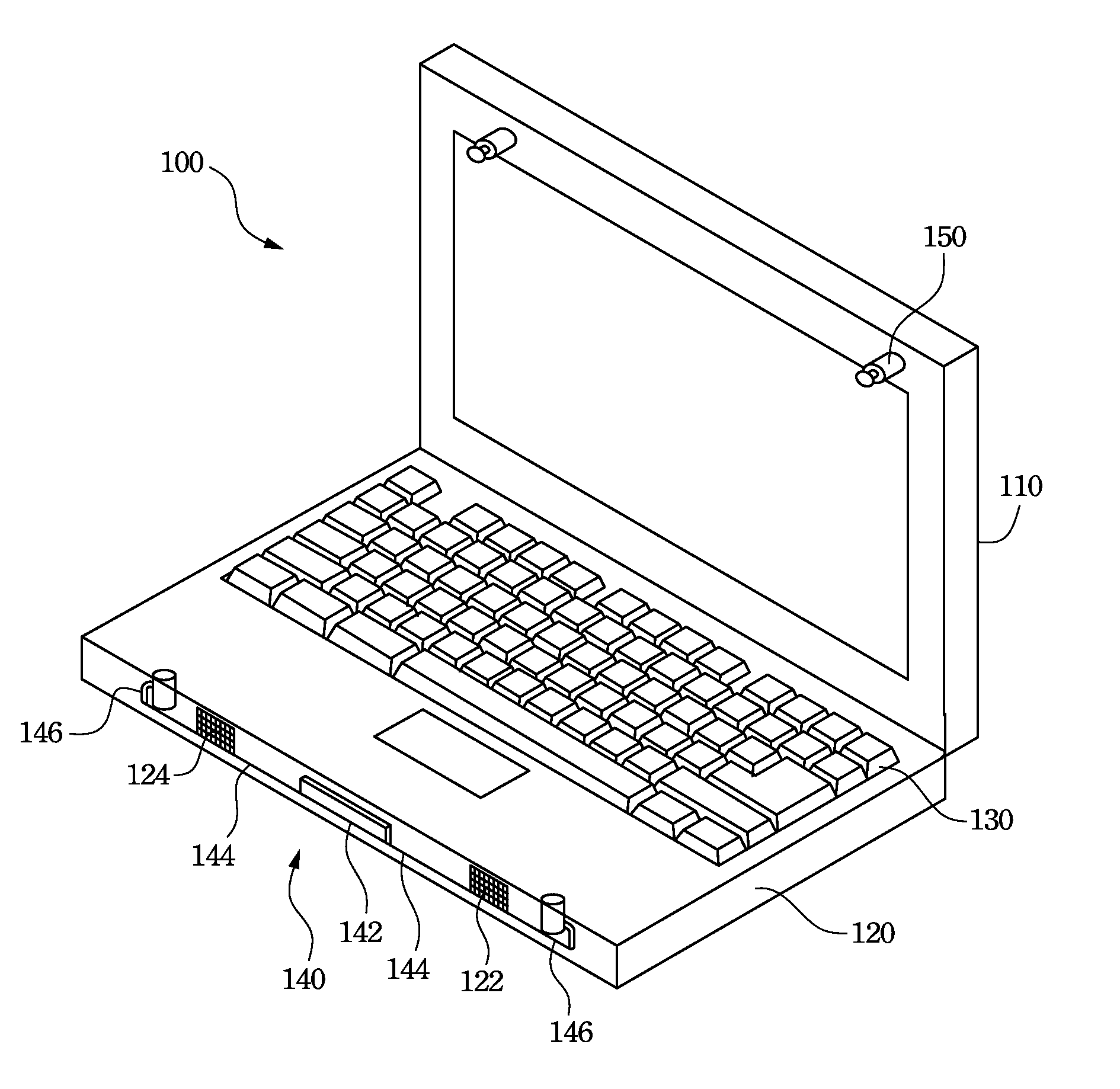
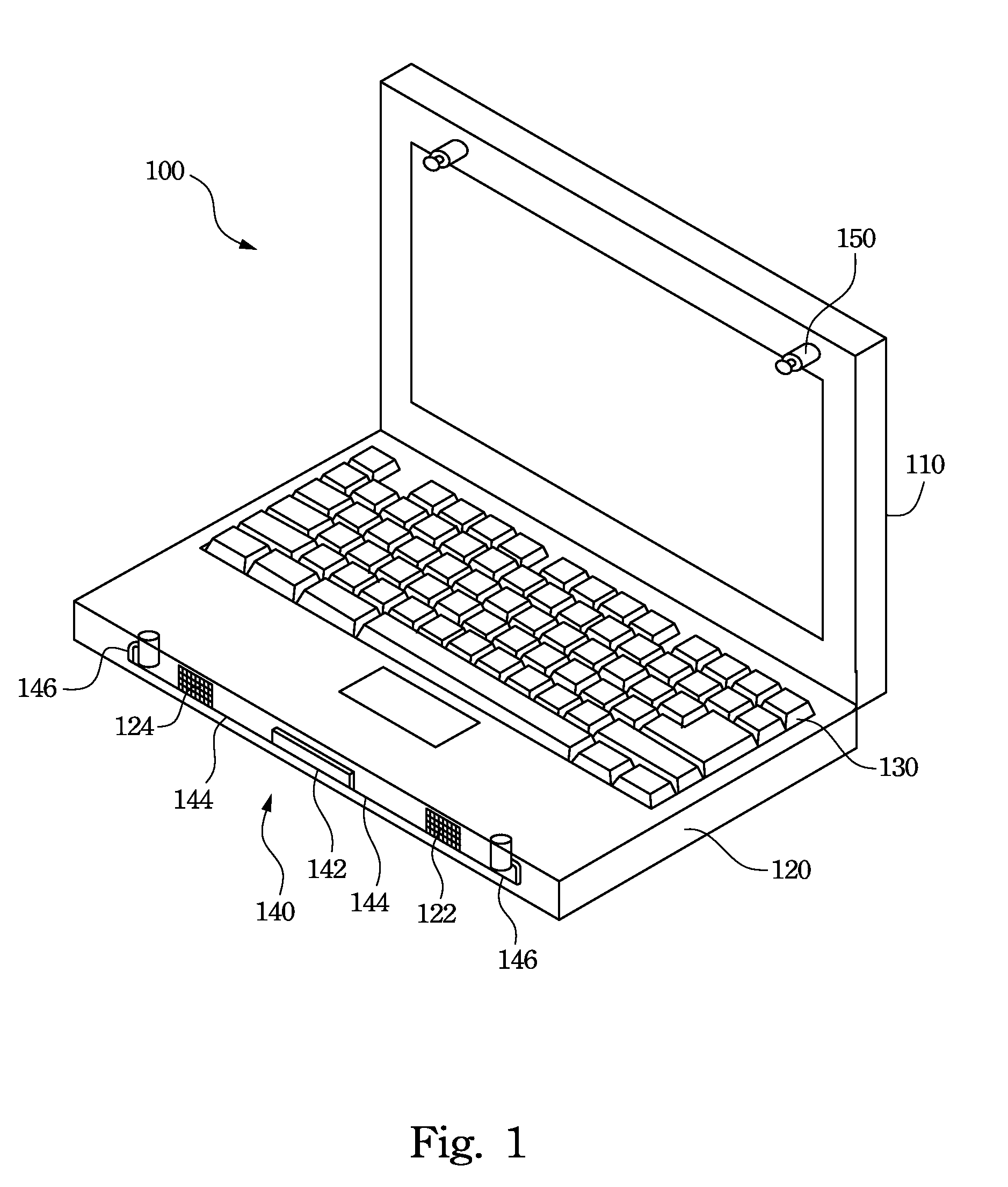
[0019]Refer to FIG. 1. FIG. 1A illustrates a preferred embodiment of a latching structure of a mobile electronic device according to the present invention. The latching structure 140 is equipped in a mobile electronic device 100 to lock a first shell and a second shell of the mobile electronic device 100. The latching structure 140 is configured in the first shell while the lock pin is configured in the second shell. The first shell and the second shell are, for example, a display 110 and a base 120 respectively. In this embodiment, the latching structure 140 is configured in the base 120 while the lock pin 150 is configured in the display 110. T...


PUM


Abstract

A latching structure of a mobile electronic device includes a button module, at least one lock pin, at least one linking rod, and at least one hook module respectively disposed in a base and a display of the mobile electronic device. One end of the linking rod is coupled to the button module and another end of the linking rod is coupled to the hook module. When the button module is pressed, the button module drives the linking rod to force the hook module to release the lock pin so as to allow the user opening the display from the base of the mobile electronic device.

Description

RELATED APPLICATIONS[0001]This application claims priority to Taiwan Application Serial Number 97138748, filed Oct. 8, 2008, which is herein incorporated by reference.FIELD OF THE INVENTION[0002]The present invention generally relates to a latching structure. More particularly, this invention relates to a latching structure of a mobile electronic device.BACKGROUND OF THE INVENTION[0003]With the improvements in electronic science and technology, mobile electronic devices, such as notebook computers, are becoming increasingly sophisticated. Notebooks are convenient, portable, lightweight devices capable of processing a large number of digital data and are popular to the general public.[0004]Since notebook computers are portable and powerful computation devices, notebook computers have become a necessity for most businessmen. In addition, to conveniently carry the notebook computers, some notebook computers use latching structures to lock the displays on the bases thereof. The conventi...

Claims


Application Information

Patent Timeline
Patent Type & Authority Patents(United States)
IPC IPC(8): E05C19/10E05C9/00
CPCE05B17/0037E05C9/045G06F1/1679E05B65/006E05B2015/0235E05C9/1875Y10S292/37Y10T292/0911Y10T292/0848Y10T292/0931Y10T292/1056Y10T292/0951Y10T292/0854Y10T292/0926Y10T292/1051Y10T292/0917
Inventor CHANG, YIMINGKUO, YUNG CHIHLU, LI CHECHEN, MIN-CHUN
Owner COMPAL ELECTRONICS INC
Why Eureka
Try Eureka