Driving belt and method for assembling same

a technology of driving belts and components, applied in the field of driving belts, can solve the problems of difficult to fit the pieces or last several pieces of interlinked elements with the rings, the difficulty of overlapping the carriers arranged parallel to each other, and the inability to meet the requirements of the ring thickness, so as to enhance the strength of the driving belt, the effect of efficiently utilizing the space between the protruding portions

Inactive Publication Date: 2012-02-07
TOYOTA JIDOSHA KK
View PDF20 Cites 4 Cited by
  • Summary
  • Abstract
  • Description
  • Claims
  • Application Information

AI Technical Summary

Benefits of technology

[0010]The present invention has been conceived noting the technical problems thus far described, and its object is to provide a driving belt which can be assembled easily, specifically, in which rings can be fitted easily into a recess of the element even at a final phase of a fitting work, and an assembling method thereof.

Problems solved by technology

This makes difficult to overlap the carriers arranged parallel to each other when assembling the transmission belt.
However, the pivotal movement of the element is eventually restricted especially at a final phase of such fitting operation of the rings and the elements, for example, at a stage when fitting a last piece or last several pieces of the interlinked element with the rings.
Thus, the last piece or last several pieces of the interlinked element is difficult to be fitted with the rings.

Method used


Image

  • Driving belt and method for assembling same
  • Driving belt and method for assembling same
  • Driving belt and method for assembling same

Examples


first example

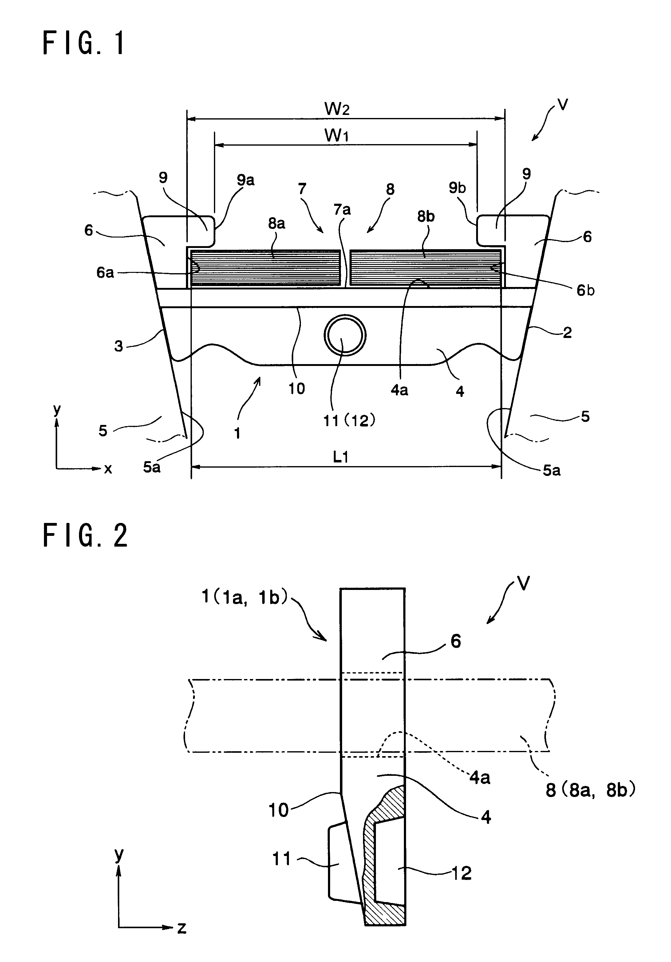
[0051]Here will be explained configurations of elements and rings constituting a driving belt V of the first example with reference to FIGS. 1 and 3. FIG. 1 shows an example of a driving belt V to be applied to a drive pulley (i.e., an input shaft side pulley) and a driven pulley (i.e., an output shaft side pulley) of a belt type continuously variable transmission so as to transmit a power between those pulleys. An element 1 includes two kinds of elements such as a first element 1a and a second element 1b. In this connection, the first element 1a mainly used in the driving belt V will be explained first of all.

[0052]The element 1a is a metal plate member comprising a base portion (or main body) 4. Both lateral faces 2 and 3 of the base portion 4, that is, both lateral ends (in the direction of x-axis in FIG. 1) of the base portion 4 are inclined. The inclined lateral faces 2 and 3 are frictionally contacted with a V-shaped groove of a drive or driven pulley 5 of the belt type contin...

second example

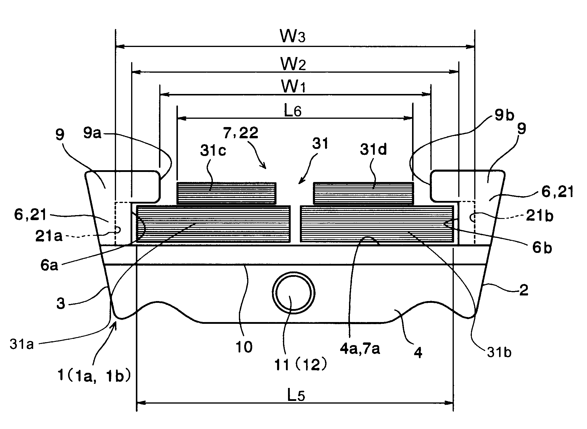
[0075]Here will be explained a second example of the element and the ring of the driving belt with reference to FIGS. 8 to 10. According to previously described first example, the width of both rings 8a and 8b constituting the ring 8 is entirely constant. On the other hand, according to the second example, the ring 8 also comprises two rings but each ring comprises two layers of different widths. Specifically, the width of both inner rings is constant entirely, and a width of each outer ring is also constant entirely but narrower than that of the inner ring. The remaining elements of the second example are identical to those of the first example shown in FIGS. 1 to 7, so further explanation of the elements in common with those in the first Example will be omitted by allotting common reference numerals. Here, the configuration of the recess 22 of the second element 1b is illustrated by a broken line in FIGS. 8 and 10.

[0076]In the example shown in FIG. 8, two lines of rings 31a and 31...


PUM

PropertyMeasurementUnit
widthsaaaaaaaaaa
distanceaaaaaaaaaa
widthaaaaaaaaaa

Abstract

A driving belt and method of assembling the same, which can fit rings with elements easily even at a final phase of fitting work. In a driving belt, two rows of endless rings are accommodated and held parallel to each other in a recess of a plurality of elements interlinked annularly in a manner to situate the recess to open to an outer circumferential side and in a manner to pivot with respect to the adjoining elements, and the element includes plural types of elements having different configurations of the recess.

Description

TECHNICAL FIELD[0001]This invention relates to a driving belt, in which a plurality of plate elements interlinked with one another in a circular manner is fastened by an endless annular ring, and to an assembling method thereof.BACKGROUND ART[0002]In the prior art, a geared transmission capable of changing a gear stage thereof stepwise, and a continuously variable transmission capable of varying a speed change ratio steplessly are available as a transmission mechanism for transmitting power between rotary members. For example, a belt-type continuously variable transmission and a toroidal-type continuously variable transmission are known as the continuously variable transmission. Specifically, the belt-type continuously variable transmission is a transmission varying a speed change ratio continuously using a pair of drive pulleys and a pair of driven pulleys, and a driving belt applied to those pulleys. The known endless driving belt used in such belt-type continuously variable trans...

Claims


Application Information

Patent Timeline
Patent Type & Authority Patents(United States)
IPC IPC(8): F16G5/16
CPCB29D29/10F16G5/16Y10T29/49826F16H9/24
Inventor KOBAYASHI, DAISUKE
Owner TOYOTA JIDOSHA KK
Why Eureka
Try Eureka