System for hot solids combustion and gasification

a hot solids combustion and gasification technology, applied in the field of co2 capture, can solve the problems of substantial capital equipment and land space, insufficient reductions to achieve atmospheric cosub>2 /sub>stabilization, and insufficient reductions to achieve the effect of atmospheric cosub>2 /sub>stabilization

Active Publication Date: 2012-02-07
AIR PROD & CHEM INC +1
View PDF5 Cites 89 Cited by
  • Summary
  • Abstract
  • Description
  • Claims
  • Application Information

AI Technical Summary

Benefits of technology

[0011]In another embodiment, the chemical looping system can be retrofit to an existing power generation system, and the product gas is CO2. In this embodiment, the boiler that typically forms part of an existing power plant is eliminated. The heat normally transferred from the boiler to generate superheated steam is now obtained from the chemical looping system. For example, heat exchanger means can be positioned in the oxidizer reactor for converting at least one of water, water vapor and steam into superheated steam, the superheated steam being fed directly into a steam turbine. However, the present invention is not limited in this regard as the above-described heat exchanger means can be positioned essentially anywhere within the chemical looping system where sufficient heat is present. In this embodiment, the chemical looping system is also configured to capture CO2 generated therein. Similar to the above-described embodiment, coal preparation devices forming part of an existing power generation system could be used to prepare coal and limestone for the chemical looping system. The chemical looping system would be configured so that during operation, it would produce superheated steam by transferring heat generated in the oxidizer reactor or other area of the chemical looping system to the heat exchanger means. The CO2 produced and captured can be used in an Enhanced Oil Recovery (EOR) process or it can be sequestered. The steam produced is sent to an existing steam turbine forming part of the retrofitted power generation system, thereby eliminating the need for the boiler in the existing power plant.
[0012]In yet another embodiment, the product gas is CO2 and the boiler forming part of the existing power generation system to which the chemical looping system is retrofit is used as the oxidizer reactor. Using the existing boiler as the oxidizer reactor avoids the need to include the oxidizer, and superheat steam production equipment in the chemical looping system. In this embodiment, the reducer reactor is in fluid communication with the first separator for the receipt of CaS and gas generated in the reducer. The first separator then discharges CO2 from the first outlet for sequestration and CaS / gas from a second outlet in fluid communication with the first solids valve. The first solids valve has a first outlet in fluid communication with the reducer reactor and the second outlet in fluid communication with the existing boiler that is utilized and configured in this embodiment to operate as an oxidizer reactor. The boiler / oxidizer reactor is in fluid communication with the second separator for discharging CaSO4 / gas into an inlet defined by the second separator. Nitrogen (N2) is discharged from a first outlet defined by the second separator and CaSO4 / gas is discharged from a second outlet defined by this second separator that is in turn in fluid communication with a second solids control valve. The second solids control valve is in fluid communication with the reducer reactor and the boiler / oxidizer reactor for introducing CaSO4 therein.

Problems solved by technology

Although substantial reductions in emissions of CO2 could be achieved by an increase in efficiency of energy conversion and utilization, such reductions may not be sufficient to achieve atmospheric CO2 stabilization.
A substantial energy penalty is incurred using this process due to the large power requirements of producing pure oxygen.
Unfortunately, substantial capital equipment and land space are required.

Method used


Image

  • System for hot solids combustion and gasification
  • System for hot solids combustion and gasification
  • System for hot solids combustion and gasification

Examples


Embodiment Construction

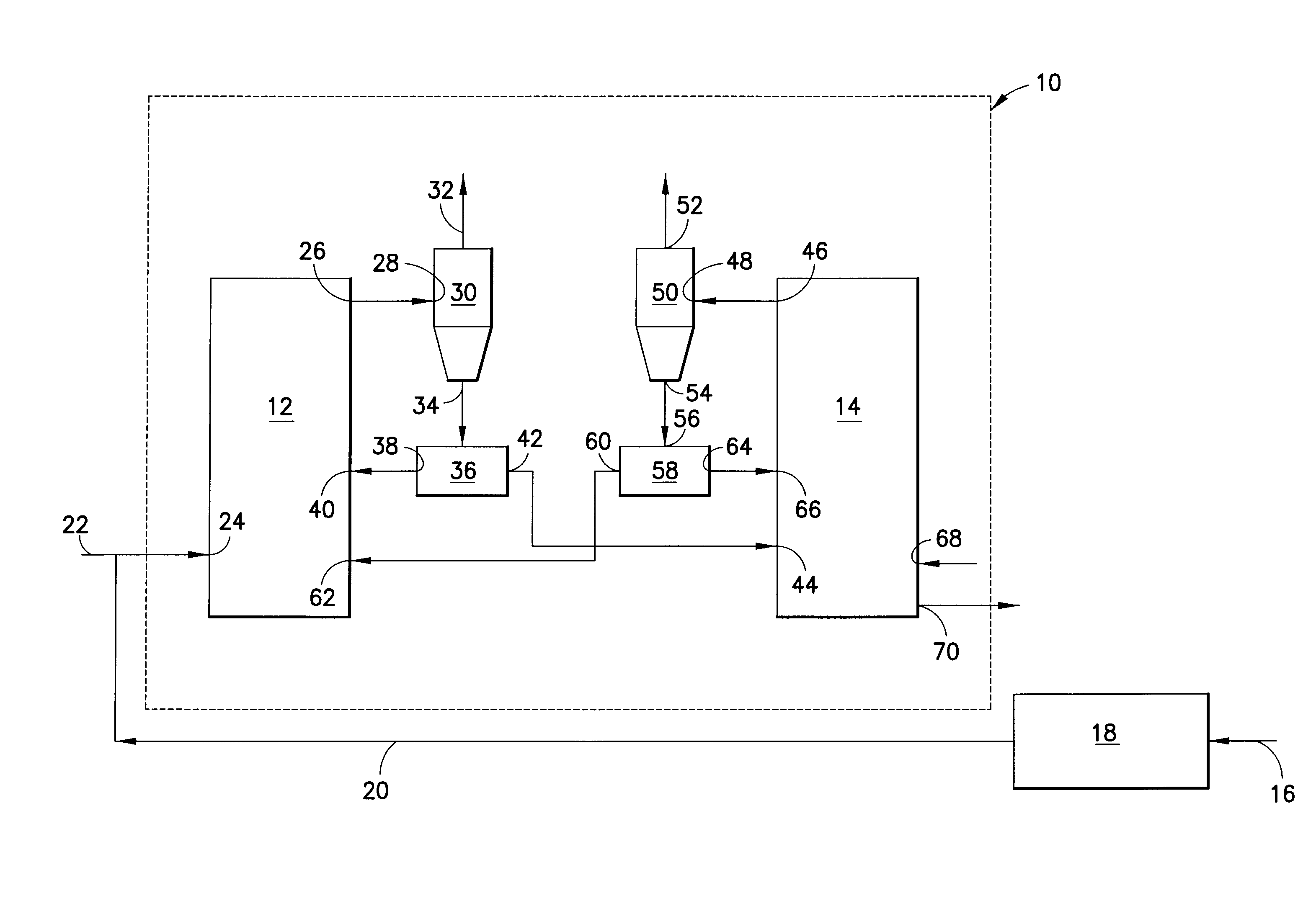
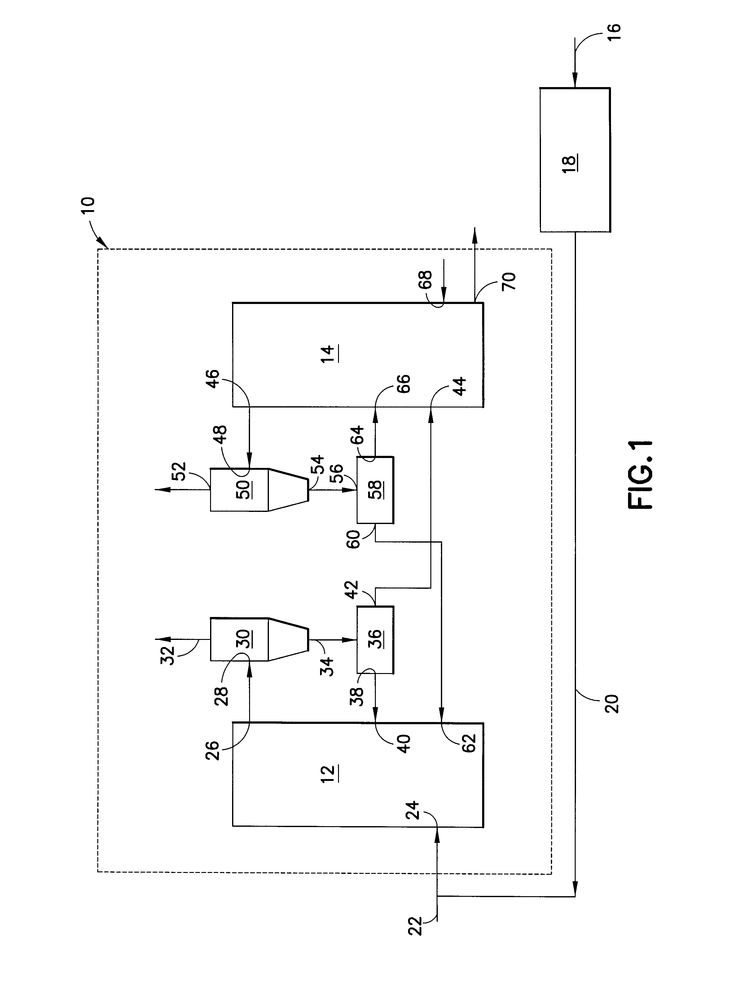
[0022]As shown in FIG. 1, a chemical looping system is generally designated by the reference number 10 and is encompassed by the dotted lines shown in the figure. Chemical looping is described in U.S. Pat. No. 7,083,658, the contents of which are incorporated in entirety by reference herein. The chemical looping system 10 includes an endothermic reducer reactor 12 and an oxidizer reactor 14. Fuel, in the form of coal and CaCO3 (limestone) are fed via conduit 16 into a coal preparation device 18. The coal preparation device 18 can form part of an existing power plant such as, but not limited to, a pulverized coal or fluidized bed power plant, to which a chemical looping system can be retrofit. The coal and CaCO3 are fed through conduit 20 to an inlet 24 into the reducer reactor. Steam is also fed via conduit 22 into the reducer reactor 12 via the inlet 24. However, the coal, CaCO3 and the steam can also each be fed into the reducer reactor 12 through separate inlets. Moreover, while ...


PUM


Abstract

In a retrofit system for hot solids combustion and gasification, a chemical looping system includes an endothermic reducer reactor 12 having at least one materials inlet 22 for introducing carbonaceous fuel and CaCO3 therein and a CaS / gas outlet 26. A first CaS inlet 40 and a first CaSO4 inlet 64 are also defined by the reducer reactor 12. An oxidizer reactor 14 is provided and includes an air inlet 68, a CaSO4 / gas outlet 46, a second CaS inlet 44, and a second CaSO4 inlet 66. A first separator 30 is in fluid communication with the CaS / gas outlet 26 and includes a product gas and a CaS / gas outlet 32 and 34 from which CaS is introduced into said first and second CaS inlets. A second separator 50 is in fluid communication with the CaSO4 / gas outlet 46 and has an outlet 52 for discharging gas therefrom, and a CaSO4 outlet from which CaSO4 is introduced into the first and second CaSO4 inlets 62, 66. The chemical looping system is in fluid communication with at least a portion of an existing power generation system.

Description

CROSS-REFERENCE TO RELATED APPLICATIONS[0001]This application claims the benefit of U.S. provisional application No. 61 / 085,248 filed Jul. 31, 2008 and U.S. provisional application No. 61 / 098,262 filed Sep. 19, 2008, the contents of which are incorporated herein by reference in their entirety.FIELD OF THE INVENTION[0002]The disclosure herein is generally directed to the capture of CO2 in existing power plants and is more particularly directed to retrofitting existing power generation systems with a chemical looping system.BACKGROUND OF THE INVENTION[0003]Fossil fuel power stations conventionally use steam turbines to convert heat into electricity. Conversion efficiencies of new steam power stations can exceed 40% LHV. New supercritical steam boiler designs, relying on new materials, allow higher steam temperatures and pressures, providing efficiencies of close to 50% LHV and further improvements might be expected. Significant advancements have also been made in combined cycle gas tu...

Claims


Application Information

Patent Timeline
Patent Type & Authority Patents(United States)
IPC IPC(8): B01J7/00
CPCC10J3/54C10J3/721C10J3/725C10J2300/0996C10J2300/1807Y02E20/18Y02E20/16Y02P20/129
Inventor CHIU, JOHN H.ANDRUS, HERBERT E.LILJEDAHL, GREGORY N.THIBEAULT, PAUL R.
Owner AIR PROD & CHEM INC
Why Eureka
Try Eureka