Differential amplifier with improved zero-point calibration

Active Publication Date: 2012-02-07
NAT SEMICON CORP
View PDF2 Cites 8 Cited by
  • Summary
  • Abstract
  • Description
  • Claims
  • Application Information

AI Technical Summary

Benefits of technology

[0013]In one embodiment of the invention, a system for amplification of a differential input signal is disclosed. The system comprises a first resistor coupled as a portion of a circuit branch from a first virtual short to a second virtual short, where the first and second virtual shorts are driven respectively by a first and a second amplifier configured for negative feedback. The system also comprises a three-terminal device having a first terminal coupled to the first resistor, a second terminal coupled to an output of the second amplifier, and a high impedance output terminal passing a current substantially controlled by a difference

Problems solved by technology

However, the height of a single child would be disturbed from the norm because the fulcrum of the see-saw and the ground directly beneath the child could be at different elevations due to the wave-like movement of the ground during the earthquake.
However, the same cannot be said for the resistors in the second stage.
Although this can improve the CMRR of the circuit, both app

Method used


Image

  • Differential amplifier with improved zero-point calibration
  • Differential amplifier with improved zero-point calibration
  • Differential amplifier with improved zero-point calibration

Examples


Embodiment Construction

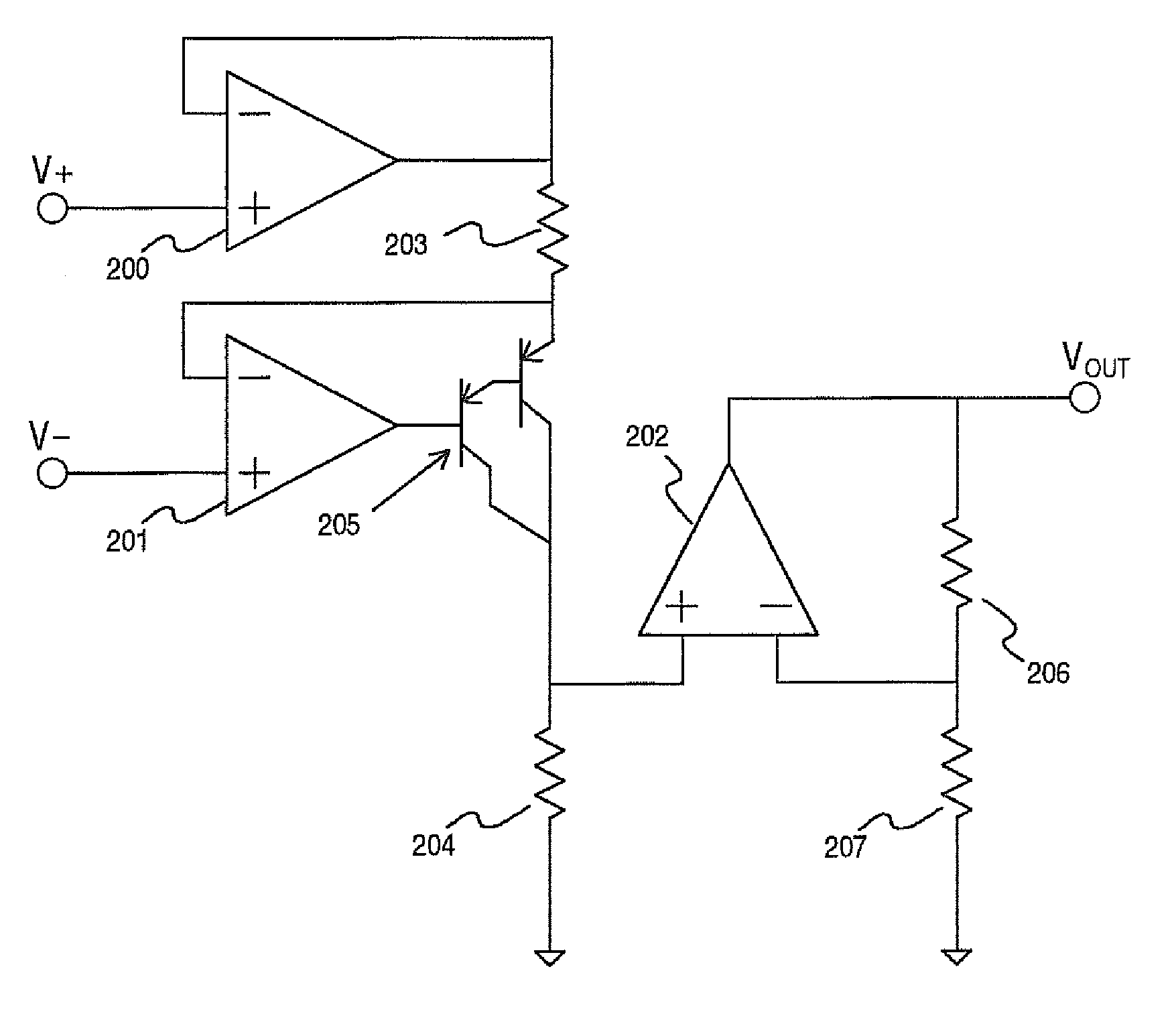
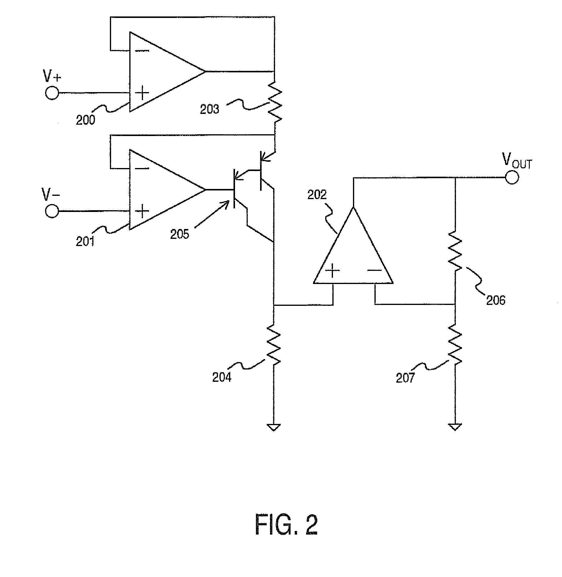
[0019]Reference now will be made in detail to embodiments of the disclosed invention, one or more examples of which are illustrated in the accompanying drawings. Each example is provided by way of explanation of the present technology, not as a limitation of the present technology. In fact, it will be apparent to those skilled in the art that modifications and variations can be made in the present technology without departing from the spirit and scope thereof. For instance, features illustrated or described as part of one embodiment may be used with another embodiment to yield a still further embodiment. Specific examples of these concepts include how resistors in block diagrams represent any form of resistive element including potentiometers, and how diagrammed circuits may be implemented in any physical form including on a single substrate. Thus, it is intended that the present subject matter covers such modifications and variations as come within the scope of the appended claims ...


PUM


Abstract

The present invention covers novel approaches to the differential amplification of an input signal. Embodiments of the present invention have precise gain, swing to within micro-volts (μV) of ground, and have high CMRR without the need for precision resistors or tuned potentiometers. Embodiments of the present invention are particularly suited for the amplification of an instrumentation signal for delivery to an analog-to-digital converter. Examples of such signals include the product of a strain-gauge front end, a temperature sensor front end, and certain devices for bioelectronics detection. Embodiments of the present invention which are systems for amplification of a differential input signal can comprise a differential input stage transconducing a differential voltage input signal into a single-ended intermediate current signal using a follower transconductance amplifier, and a single-ended output stage comprising an amplifier producing an output voltage across a resistor network that forms a negative feedback network of the amplifier.

Description

FIELD OF THE INVENTION[0001]The invention relates generally to amplifier circuits and systems, and more specifically to differential amplifiers circuits.BACKGROUND OF THE INVENTION[0002]Amplifiers are systems that increase the power of a signal. An electronic amplifier takes power from a power supply and shapes its output to match the input signal. The first electronic amplifiers were used in communication systems. One of the earliest examples of such a circuit is the Audion described in U.S. Pat. No. 841,386 to De Forest. Today, amplifiers are an indispensible portion of nearly all analog and mixed-signal electronic systems. Amplifiers have myriad uses including increasing the power of a communication signal for transmission through a wireless network, adjusting the strength of an audio signal to a desired volume, and making a sensor signal more readily convertible to a digital format.[0003]In electronic circuit design, a differential architecture is one in which the carried signal...

Claims


Application Information

Patent Timeline
IPC IPC(8): H03F3/45
CPCH03F3/45475H03F3/45941H03F2200/261H03F2200/411H03F2203/45528
Inventor PEASE, ROBERT ALLEN
Owner NAT SEMICON CORP
Why Eureka
Try Eureka