Occupancy sensors programmed to determine loss of lamp life as lamp is used

a technology of occupancy sensors and lamps, applied in the field of occupancy sensors, can solve the problems of increasing lamp replacement costs and environmental waste, hazardous or dangerous conditions, and nothing currently known that can automatically alert users to the pending end of life of lamps

Active Publication Date: 2012-02-07
ABL IP HLDG
View PDF14 Cites 17 Cited by
  • Summary
  • Abstract
  • Description
  • Claims
  • Application Information

AI Technical Summary

Benefits of technology

[0008]In accordance with the invention, a programmable occupancy sensor automatically determines loss of lamp life of a fluorescent lamp as the lamp is being used. An algorithm implemented in software or firmware and executing on preferably the sensor's microcontroller calculates lamp loss taking into account the fluorescent lamp's actual hours of operation (i.e., actual on time) and the number of off / on transitions. In one embodiment of the invention, the sensor can communicate to a user lamp life status (e.g., the percentage of lamp life remaining or used) and can alert a user when a lamp is nearing its end of life and should be replaced via a programmable push button and one or more LEDs (light emitting diodes) located on the sensor. In another embodiment of the invention, a networked occupancy sensor coupled to a display device either directly or through a lighting control system can provide a user with the same and more detailed lamp life information via graphical displays and optional audible alerts. Occupancy sensors of the invention can advantageously avoid the inconvenience or dangerous and / or hazardous conditions caused by burnt out lamps without wasting any lamps that may still have useful lamp life remaining.
[0010]Occupancy sensors of the invention can therefore be advantageously used to save energy and extend fluorescent lamp life automatically by turning off lamps when not needed, by reducing off / on transitions with an optimal time delay based on observed occupancy patterns, and by continuously monitoring occupancy patterns to ensure that the sensor is always operating with an optimal time delay.

Problems solved by technology

Replacing lamps according to a schedule may unnecessarily increase lamp replacement costs and environmental waste if the replaced lamps still have many hours of lamp life remaining.
Replacing lamps after they burn out causes at least some inconvenience and may result in hazardous or dangerous conditions until the lamps are replaced.
Unfortunately, nothing is currently known that can automatically alert a user to a lamp's pending end of life based on actual usage of the lamp.
That is, each off / on transition reduces the lamp's operating hours by a small amount.
Thus, if lights are turned off and then back on again after too short a period of off time, more lamp life is lost by the affect of the lights turning back on than is saved by the short off time.
However, this feature may not extend lamp life if the actual occupancy pattern does not conform to the time delay.
However, nothing is currently known that can automatically select the optimal time delay based on actual occupancy patterns.
Thus, a user is likely to select a time delay based on a predicted occupancy pattern, which may or may not result in any lamp life savings.

Method used


Image

  • Occupancy sensors programmed to determine loss of lamp life as lamp is used
  • Occupancy sensors programmed to determine loss of lamp life as lamp is used
  • Occupancy sensors programmed to determine loss of lamp life as lamp is used

Examples


Embodiment Construction

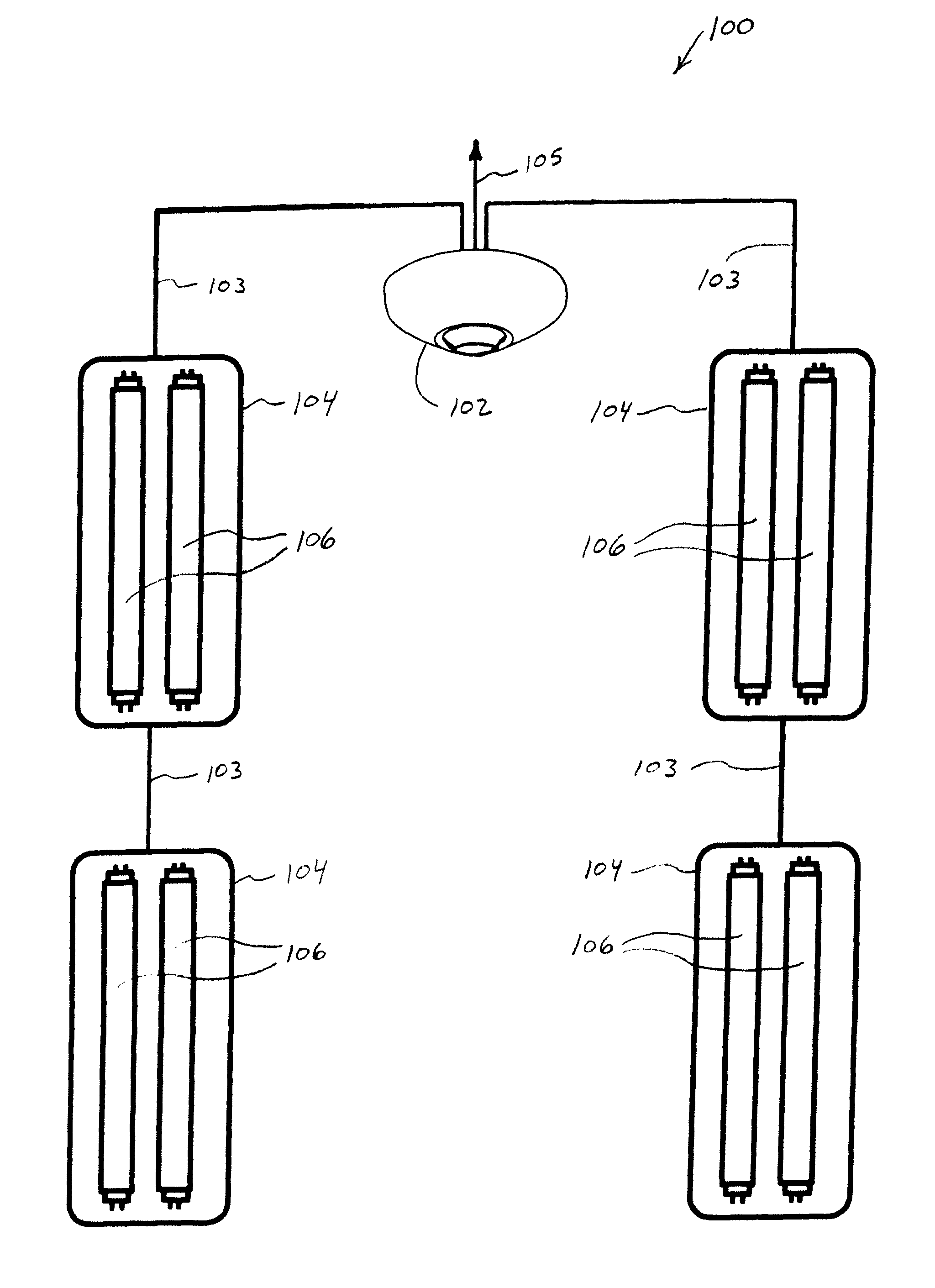
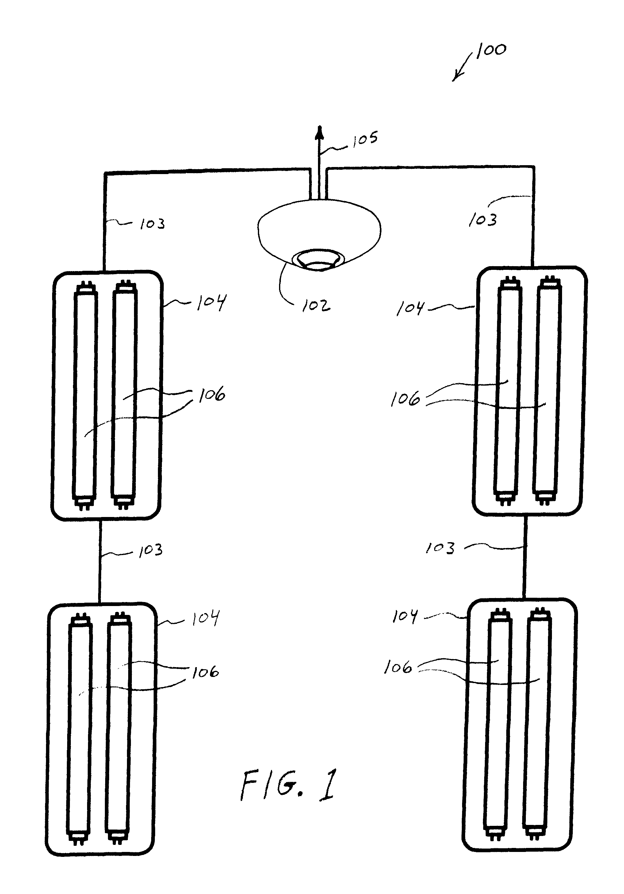
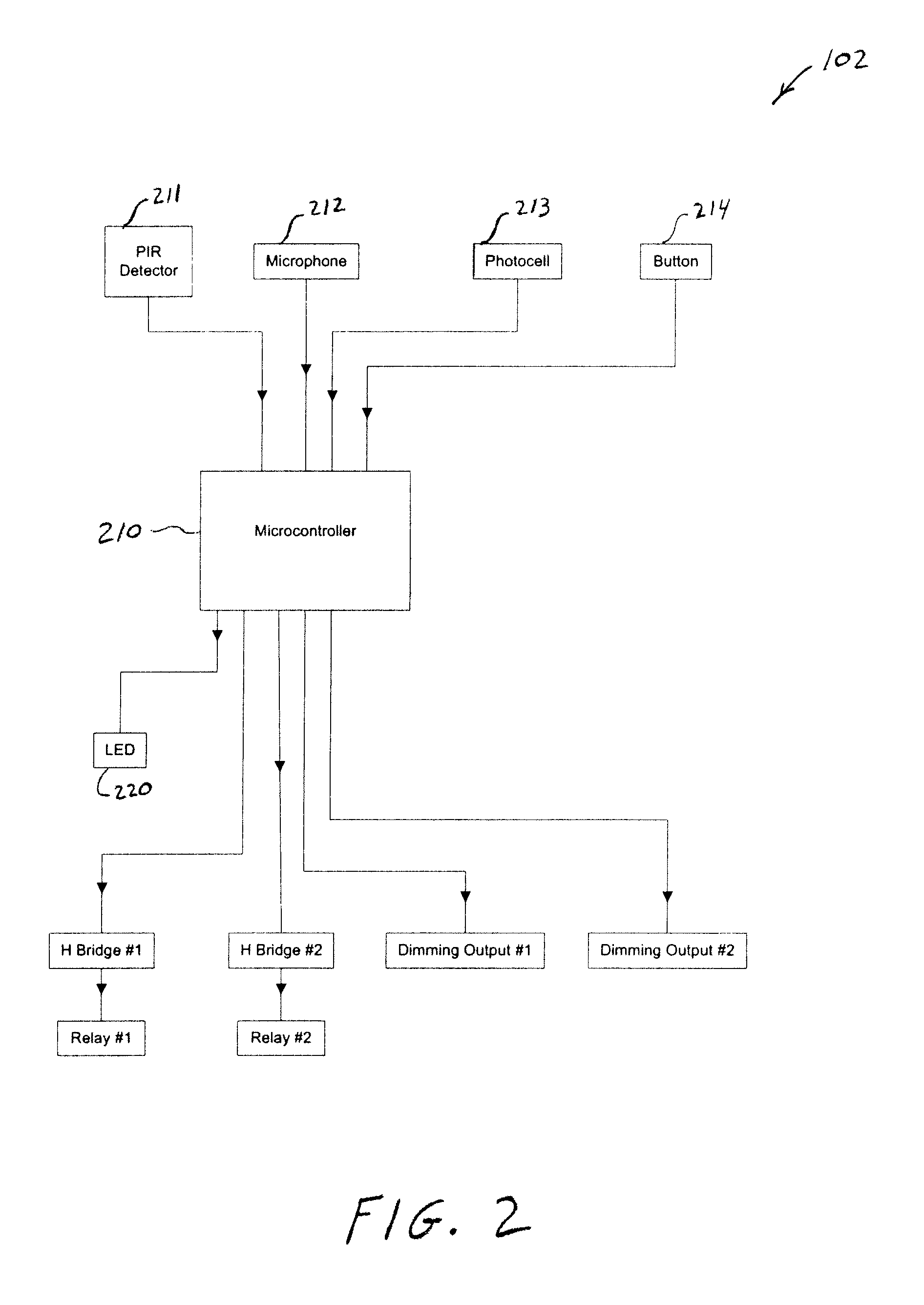
[0026]FIG. 1 shows a lighting control zone 100 that includes an occupancy sensor 102 coupled to four fluorescent lighting units 104, each containing two fluorescent lamps 106. Note that the number of lighting units coupled to sensor 102 and the number of fluorescent lamps 106 per lighting unit is merely illustrative and can be more or less than that shown. A lighting control zone may be, for example, an individual room or office, a classroom, a manufacturing area, a lobby, or other defined area whose lighting is controlled by an occupancy sensor. In this embodiment, occupancy sensor 102 is a ceiling mounted 360° sensor typically placed in private offices, vestibules, or small rooms. Sensor 102 is a line voltage sensor and has an integrated relay connected to power via Class 1 wiring 105 and to fluorescent lighting units 104 via Class 1 wiring 103. Sensor 102 also has an integrated microcontroller and firmware, and the ability to operate with preferably passive infrared (PIR) detecti...


PUM


Abstract

Programmable occupancy sensors that control the on / off operation of a fluorescent lamp automatically determine loss of lamp life as the lamp is used. The programmable occupancy sensors can provide lamp life status and can automatically alert a user when a lamp is nearing its end of life and should be replaced. The occupancy sensors are also programmable to automatically maximize lamp life and energy savings by selecting an optimal time delay from among a number of selectable time delays at which to operate the sensor. The selection is based on an occupancy pattern sensed by the sensor over a given period of time. The optimal time delay, which prevents the lamp from turning off immediately after last sensing occupancy, extends lamp life by limiting the number of lamp off / on transitions, which shortens lamp life, in view of overall energy usage and lamp usage.

Description

FIELD OF THE INVENTION[0001]The invention relates to occupancy sensors. More particularly, the invention relates to occupancy sensors programmed to automatically determine loss of lamp life as a fluorescent lamp controlled by the occupancy sensor is used.BACKGROUND OF THE INVENTION[0002]Lamps typically are replaced either according to a pre-determined schedule or after they burn out. The pre-determined schedule is usually a rough estimate of when lamps will be near their end of life based on the lamp's published lamp life (defined in hours of operation) and the lamp's expected usage. Neither replacement method is particularly desirable. Replacing lamps according to a schedule may unnecessarily increase lamp replacement costs and environmental waste if the replaced lamps still have many hours of lamp life remaining. Replacing lamps after they burn out causes at least some inconvenience and may result in hazardous or dangerous conditions until the lamps are replaced. Unfortunately, no...

Claims


Application Information

Patent Timeline
Patent Type & Authority Patents(United States)
IPC IPC(8): G05B23/02
CPCF21V23/0442H05B37/0227H05B41/2985Y02B20/40H05B47/13
Inventor ZAVERUHA, RYAN A.PLATNER, BRIAN P.HAHN, BENJAMIN C.
Owner ABL IP HLDG
Why Eureka
Try Eureka