In-vehicle system, detailed warning lamp information notification system, and server system

a warning lamp and information notification system technology, applied in navigation instruments, anti-theft devices, instruments, etc., can solve the problems of inability of users unfamiliar with the warning lamp to pinpoint faults or poorly maintained, inconvenient for users,

Inactive Publication Date: 2010-07-06
DENSO CORP
View PDF48 Cites 13 Cited by
  • Summary
  • Abstract
  • Description
  • Claims
  • Application Information

AI Technical Summary

Benefits of technology

[0005]An in-vehicle system according to the present invention is so constructed that the following is implemented: when the warning lamp on a meter panel lights up or flashes, a controlling means causes a notifying means to provide detailed warning lamp information about the lighted or flashing warning lamp. Thus, when the warning lamp on the meter panel lights up or flashes, the user can be swiftly informed of the description of the content of the warning, coping strategies, and the like. This can make it unnecessary for the user to spend time and effort looking for a service manual and opening the service manual and searching for appropriate pages, and can enhance user-friendliness.
[0006]This in-vehicle system may be so constructed that the following is implemented: when the warning lamp on the meter panel lights up or flashes, the controlling means reads detailed warning lamp information stored in a detailed warning lamp information storing means; it thereby causes the notifying means to provide detailed warning lamp information about the lighted or flashing warning lamp. This makes it possible to implement the following: detailed warning lamp information is stored in the detailed warning lamp information storing means in advance, and the user can be thereby swiftly informed of the description of the content of the warning, coping strategies, and the like through the control solely of the in-vehicle system.
[0007]The in-vehicle system may be so constructed that the following is implemented: when the warning lamp on the meter panel lights up or flashes, the controlling means causes a communication line to be established between a first communicating means and the server system and the first communicating means to receive detailed warning lamp information from the server system; it thereby causes the notifying means to provide detailed warning lamp information about the lighted or flashing warning lamp. This makes it possible to implement the following: the communication line is established between the first communicating means and the server system, and the first communicating means is caused to receive detailed warning lamp information from the server system; the user can be thereby swiftly informed of the description of the content of the warning, coping strategies, and the like through the collaborative control of the in-vehicle system and the server system.

Problems solved by technology

A user who is unfamiliar with these warning lamps may be incapable of pinpointing what is faulty or poorly maintained even when the user sees a lighted or flashing warning lamp.
This is inconvenient for users because they take a lot of trouble with looking for a service manual or searching the service manual for appropriate pages.

Method used


Image

  • In-vehicle system, detailed warning lamp information notification system, and server system
  • In-vehicle system, detailed warning lamp information notification system, and server system
  • In-vehicle system, detailed warning lamp information notification system, and server system

Examples


first embodiment

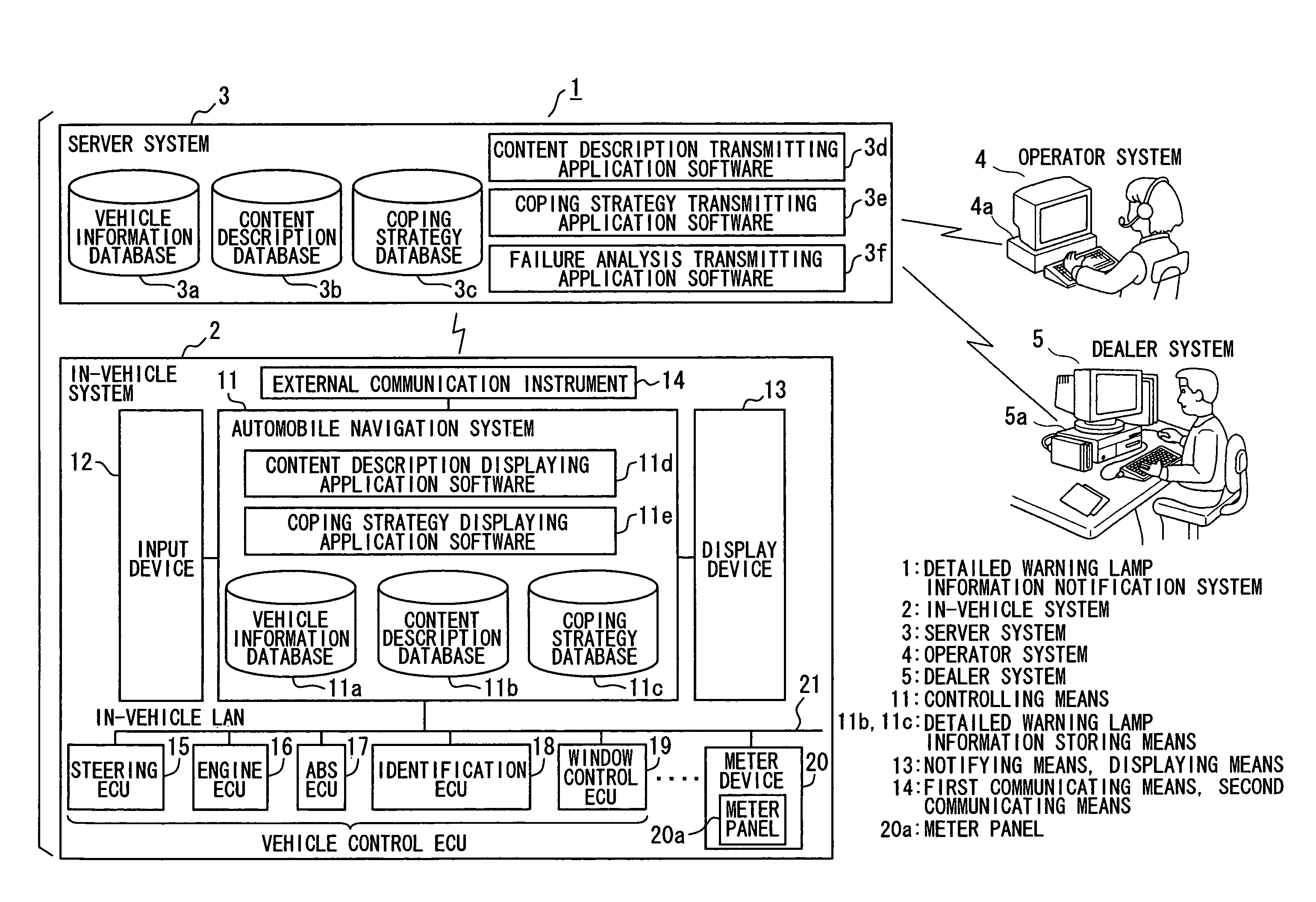
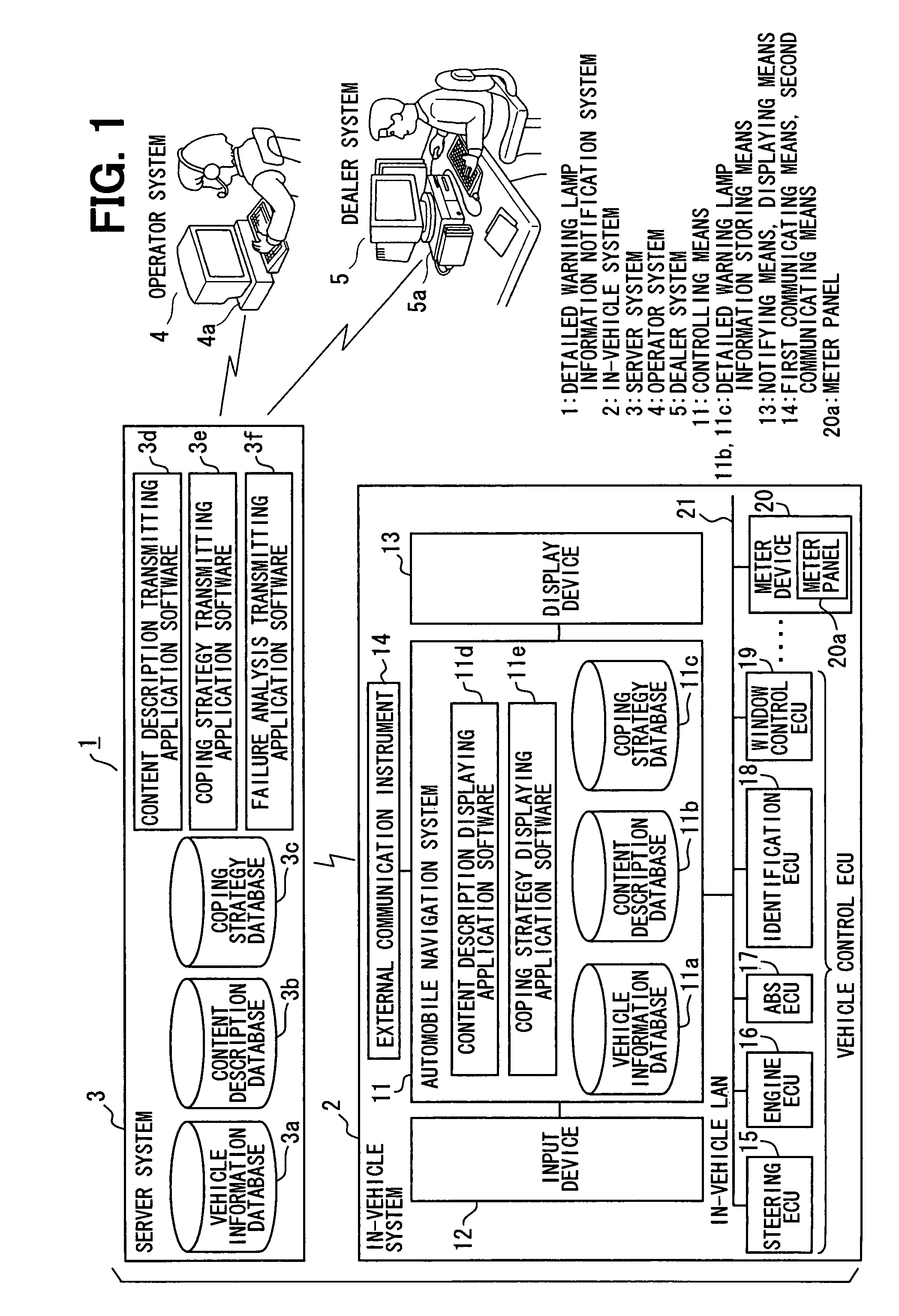
[0037]Hereafter, description will be given to a first embodiment of the invention with reference to FIGS. 1 to 10. FIG. 1 schematically illustrates the overall configuration of a detailed warning lamp information notification system.

[0038]The detailed warning lamp information notification system 1 is so constructed that the following are communicatably connected with one another through a network (including the Internet, intranet, and the like): the in-vehicle system 2 mounted in a vehicle; the server system 3 installed in a central office; an operator system 4 manned by an operator; and a dealer system 5 manned by dealer's personnel.

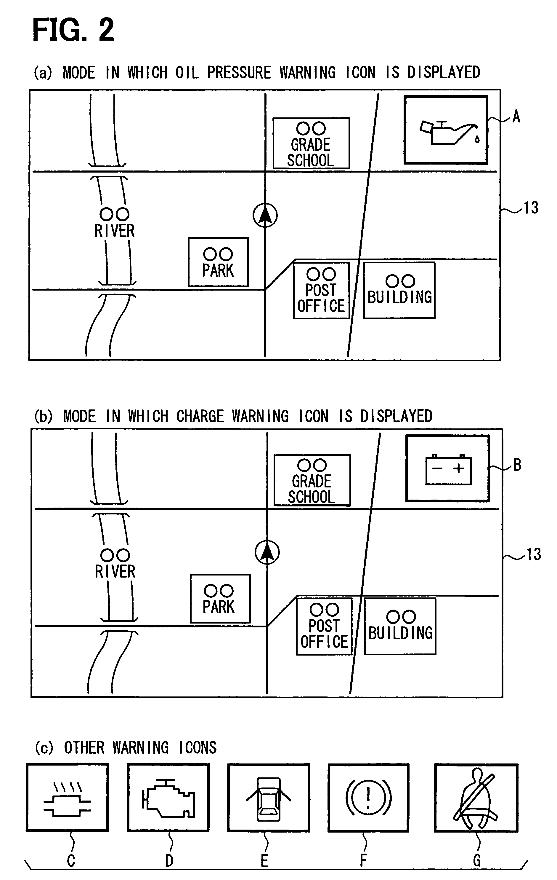
[0039]The in-vehicle system 2 includes: an automobile navigation system 11 (controlling means in the invention); an input device 12; a display device 13 (notifying means and displaying means in the invention); and an external communication instrument 14 (first communicating means and second communicating means in the invention). Further, the in-vehicle ...

second embodiment

[0084]Description will be given to a second embodiment of the invention with reference to FIG. 11 to FIG. 14. In the first embodiment, as described above, the automobile navigation system includes the vehicle information database 11a, content description database 11b, and coping strategy database 11c. In the in-vehicle system 32 in a second embodiment, the automobile navigation system 41 includes the following databases in addition to the above-mentioned databases: a user vehicle status history database 41a that can hold data related to the history of the state of a user vehicle; and a same model vehicle failure database 41b that can hold data related to failure in vehicles of the same model.

[0085]Similarly with the above-mentioned automobile navigation system 41, a server system 33 includes the following databases in addition to the vehicle information database 3a, the content description database 3b, and the coping strategy database 3c described with respect to the first embodimen...


PUM


Abstract

When a warning lamp 20a on the meter panel lights up in an in-vehicle system 1, the description of the content of warning and coping strategies about the lighted warning lamp are displayed on a display device 13. Thus, a user can be swiftly informed of the description of the content of warning and coping strategies. This can make it unnecessary for the user to spend time and effort looking for a service manual and opening the service manual and searching for appropriate pages, and can enhance user-friendliness.

Description

TECHNICAL FIELD[0001]The present invention relates to an in-vehicle system that can be mounted in a vehicle and is so constructed that a warning lamp on a meter panel lights up or flashes in correspondence with the occurrence of an anomaly in a vehicle, a detailed warning lamp information notification system so constructed that it includes the in-vehicle system and a server system, and a server system used in the detailed warning lamp information notification system.BACKGROUND ART[0002]Vehicles are so constructed that when an anomaly occurs, for example, in the pressure of engine oil, a charging system, or the like, the following takes place: the oil pressure warning lamp, the charge warning lamp, or the like on a meter panel lights up or flashes, and a user is thereby informed of the occurrence of the anomaly in the pressure of engine oil, the charging system, or the like. (Refer to Japanese patent document JP-A-2002-29364, for example.)[0003]A user who is unfamiliar with these war...

Claims


Application Information

Patent Timeline
Patent Type & Authority Patents(United States)
IPC IPC(8): B60Q1/00B60Q1/26B60Q11/00B60R25/10B60K35/00B60R16/02G01M17/007
CPCB60K35/00B60Q9/00F01M1/18G01C21/3697G07C5/0816B60K2350/108G07C5/008G08G1/205B60K2370/161
Inventor NAGATA, ASAKO
Owner DENSO CORP
Why Eureka
Try Eureka