Adjustable pneumatic supporting surface

a support surface and pneumatic technology, applied in the field of adjustable support surfaces, can solve the problems of inability to collect information, inability to implement uniform treatment measurement scales, and inability to meet modern requirements, and achieve the effects of optimizing treatment for each section, high sensor density, and high quality information

Active Publication Date: 2010-04-15
HLZ INNOVATION
View PDF73 Cites 10 Cited by
  • Summary
  • Abstract
  • Description
  • Claims
  • Application Information

AI Technical Summary

Benefits of technology

[0025]These differences in the frequency spectra can be used to provide control for the bed surface because they can provide information about the type and status of the tissue that is located over a particular sensor. When this data is measured over time, small changes in tissue condition can be detected, which are indicative of a pending skin breakdown. Thus, the control computer can make decisions in real time on how to best optimize the bed surface for the patient.
[0026]The present invention enables features which include: (1) Tissue determination on a segment by segment basis. This will enable optimized treatment for each section of the patient. For example a different therapy protocol for the adipose tissue vs. more fragile bony tissue; (2) The ability to measure the patient's mobility on the surface; (3) The ability to track the patient as they reposition themselves on the surface and provide optimized therapy wherever they are on the surface. This will include the ability to measure the position of the patient lying vs. sitting and to provide the optimal therapy protocol at all times; and (4) The ability to create diagnostic metrics on the patient's pressure relief status which can be utilized by both the professional staff and the institution's senior management to track the pressure relief situation.
[0027]The present invention utilizes multiple sensors in multiple locations on the bed surface in order to provide wide bandwidth information, which is utilized to control the surface. In accordance with one embodiment of the invention, providing a high density of sensors provides higher quality information. Furthermore, this information gathered from these multiple sensors is utilized to create diagnostic data concerning the patient's condition, which is medically useful. In addition, the diagnostic data can be combined with conventional thermography.
[0028]The present invention provides a bed surface having an improved support surface assembly, and provides a bed suitable for providing a variety of therapies to the patient through an improved feedback control system. The support surface in accordance with one embodiment of the present invention preferably includes an array of independently inflatable bladders. In one preferred embodiment of the support surface, a matrix of sensors in an array is capable of making rate-based or frequency space measurements, which can provide detailed tissue characterization information concerning the patient resting on the surface

Problems solved by technology

While these prior art alternating pressure low air loss mattresses reduce the amount of labor required to care for a patient, these mattresses fall short of modern day requirements.
Further, the prior art does not anticipate the legal environment in which hospitals operate today, where there is a need to regularly record and store surface pressure-map information to establish that the patient was receiving optimum surface therapy at all times. The current prior art not only does not anticipate these needs but furthermore, it is not capable of collecting this information because the wrong type of measurements are being used to provide the feedback information for the servo controlled mattress systems.
Attempts to implement uniform treatment measurement scales, such as the Braden Scale, have heretofore been thwarted by inexact methods of gathering statistical information relevant to the patient's bedsore condition.
However, to date, there have been no systems for continuously tracking bedsore development and status, incorporating this information along with patient mobility on the treatment surface in an automated fashion according to the recorded bedsore status and patient mobility data.

Method used


Image

  • Adjustable pneumatic supporting surface
  • Adjustable pneumatic supporting surface
  • Adjustable pneumatic supporting surface

Examples


example 1

Rate Based Measurement Utilizing Differential Pressure Sensors

[0085]Referring to FIG. 5, the floatation bladder 102, over which the measurement bladder 106 has been placed, is arranged such that the measurement bladder is in between the floatation bladder and the patient. On either end of the measurement bladder 106, pressure sensors 104, identical to that disclosed in Example 4, are attached. The analog output of these sensors is connected to, for example, a Tektronix Model 3034 Digital recording oscilloscope 108.

[0086]The floatation bladder 102 is inflated in a conventional way and tissue phantoms which represent different tissue types (which are further described in Example 5) are place on the floatation bladder in differing locations. The differentiation of different types of tissue is shown in FIGS. 6 and 7. In FIG. 6 there is shown data from an adipose tissue phantom placed in the center of the measurement bladder. In FIG. 7 there is shown data from a skin over sacrum tissue p...

example 2

Rate Based Measurement Utilizing an Accelerometer

[0090]Alternatively to using a pressure sensor at each measurement end of the floatation or measurement bladder, another embodiment of the invention is to utilize a micro-accelerometer sensor 110, for example such as one manufactured by Analog Devices (ADX L 204). As shown in FIG. 11, the accelerometer 110 is placed at one end of the floatation bladder 102, internally or externally on the bladder, and utilizes the Earth's uniform gravitational field as the reference. Other, accelerometers can also be used such as those described in U.S. Pat. Nos. 4,592,235, 3,789,674 and 4,567,771 which utilize spring mass sensors, the disclosures of which are incorporated herein by reference. In addition, other types of accelerometers such piezoelectric are also suitable for this application. The signals from the accelerometer are sent to an Oscilloscope 108 which may be connected to an area network.

[0091]As further shown in FIG. 12, the floatation b...

example 3

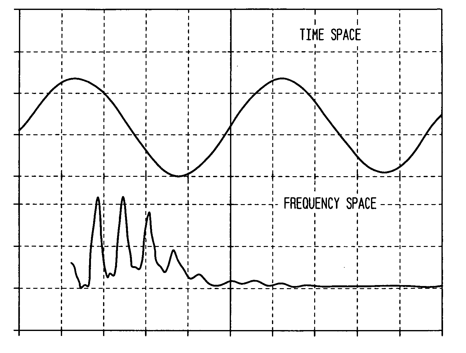
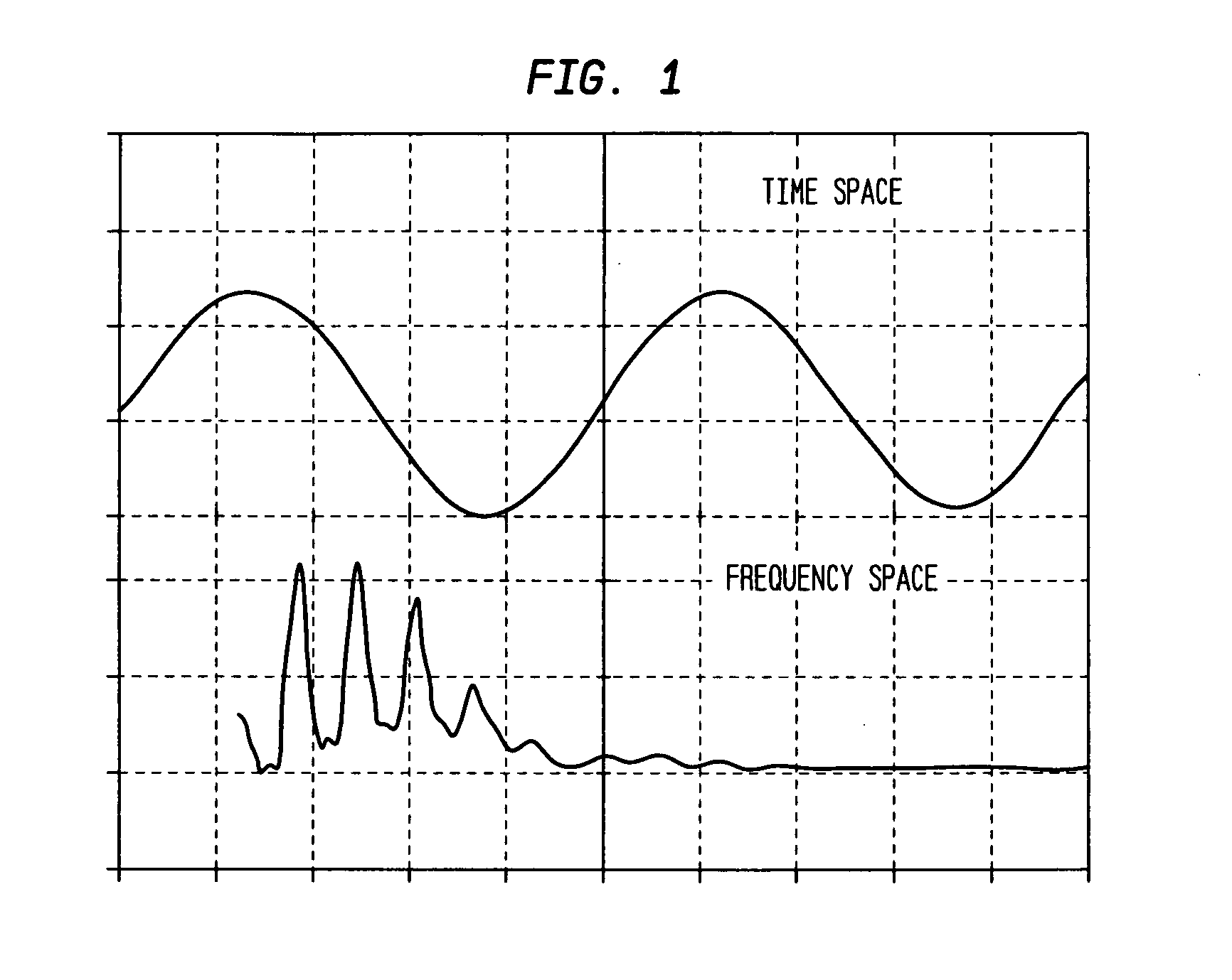
[0093]Using Fast Fourier Transform (FFT) analysis, kinetic energy is supplied by a small inflation bladder 112 in continuous inflation / deflation oscillation and an accelerometer 110 used to measure the absorption of this energy by the tissue placed over the accelerometer, see FIG. 14.

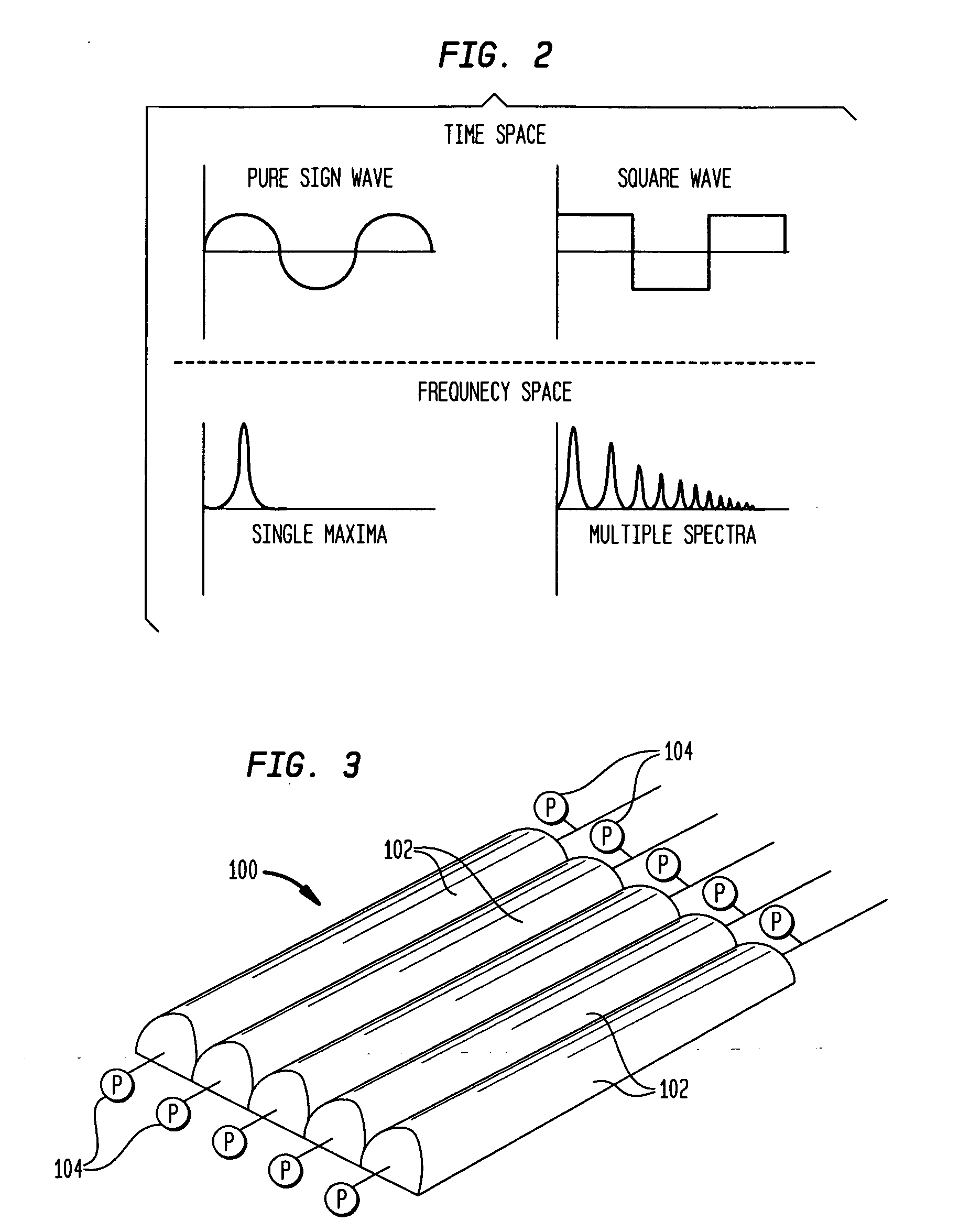
[0094]Through the use of frequency-space analysis it is possible to characterize the type of tissue which is being elevated by the surface of the inflation bladder. Although the data taken is the repetitive motion of the inflation bladder, it should be understood that FFT analysis is intended to predict the probability of frequencies in a continuous function such as a square wave oscillator. For burst functions, such as that provided by the accelerometer sensors in Examples 5-7, the software inside the oscilloscope stores the burst of data into memory and then “plays” it through the FFT algorithm many times until a spectra is derived. It should also be understood that other transforms besides FFT may be...


PUM


Abstract

An apparatus and method are adapted for characterizing human tissue type. A plurality of inflatable bladders enable the application of kinetic energy to the human tissue. Collected data responsive to the applied kinetic energy differentiates between different tissue types and patient loading. The data can be routed via a network to a remote location.

Description

CROSS REFERENCE TO RELATED APPLICATIONS[0001]This application claims the benefit of the filing date of U.S. Provisional Patent Application No. 61 / 195,073, filed Oct. 3, 2008, the disclosure of which is hereby incorporated herein by reference.BACKGROUND OF THE INVENTION[0002]The present invention relates in general to an adjustable pneumatic supporting surface, and more particularly, to adjustable pneumatic supporting surfaces responsive to variable loads and different human tissue types.[0003]Alternating pressure mattresses have been in existence for at least 75 years. Segmented air mattresses first came into existence around 1910. U.S. Pat. No. 945,234 describes a pneumatic mattress that in many respects is similar to the low air loss surfaces sold today. Other examples are disclosed in U.S. Pat. Nos. 802,526, and 1,296,359. In 1930, J. D. Hart invented the first pump-driven alternating pressure air mattress. With the exception of the more recent low air loss feature, it is in many...

Claims


Application Information

Patent Timeline
Patent Type & Authority Applications(United States)
IPC IPC(8): A61B5/103
CPCA61B5/0048A61B5/1126A61B5/445A61B5/6892A61B5/0053A61B2562/0219A61B2562/168A61G7/05776A61B5/7264A61B5/7257
Inventor HOVORKA, GEORGE
Owner HLZ INNOVATION
Why Eureka
Try Eureka