Remote observation system having transmission line for isolating local area network at data gathering site from remote monitoring site, and having provision for data request from remote monitoring site via the transmission line

a remote monitoring and transmission line technology, applied in the field of remote monitoring systems, can solve the problems of system cost and inability to be applied to some other purpos

Inactive Publication Date: 2001-01-02
MITSUBISHI ELECTRIC CORP
View PDF5 Cites 10 Cited by
  • Summary
  • Abstract
  • Description
  • Claims
  • Application Information

AI Technical Summary

Problems solved by technology

Therefore, in case of emergency, for example, the office side can obtain only insufficient information on the state of the observation object side because a report from the observation object side is the only information on the state.
This, however, has problems in that such a system becomes expensive and cannot be applied to some other purpose.

Method used


Image

  • Remote observation system having transmission line for isolating local area network at data gathering site from remote monitoring site, and having provision for data request from remote monitoring site via the transmission line
  • Remote observation system having transmission line for isolating local area network at data gathering site from remote monitoring site, and having provision for data request from remote monitoring site via the transmission line
  • Remote observation system having transmission line for isolating local area network at data gathering site from remote monitoring site, and having provision for data request from remote monitoring site via the transmission line

Examples


embodiment 2

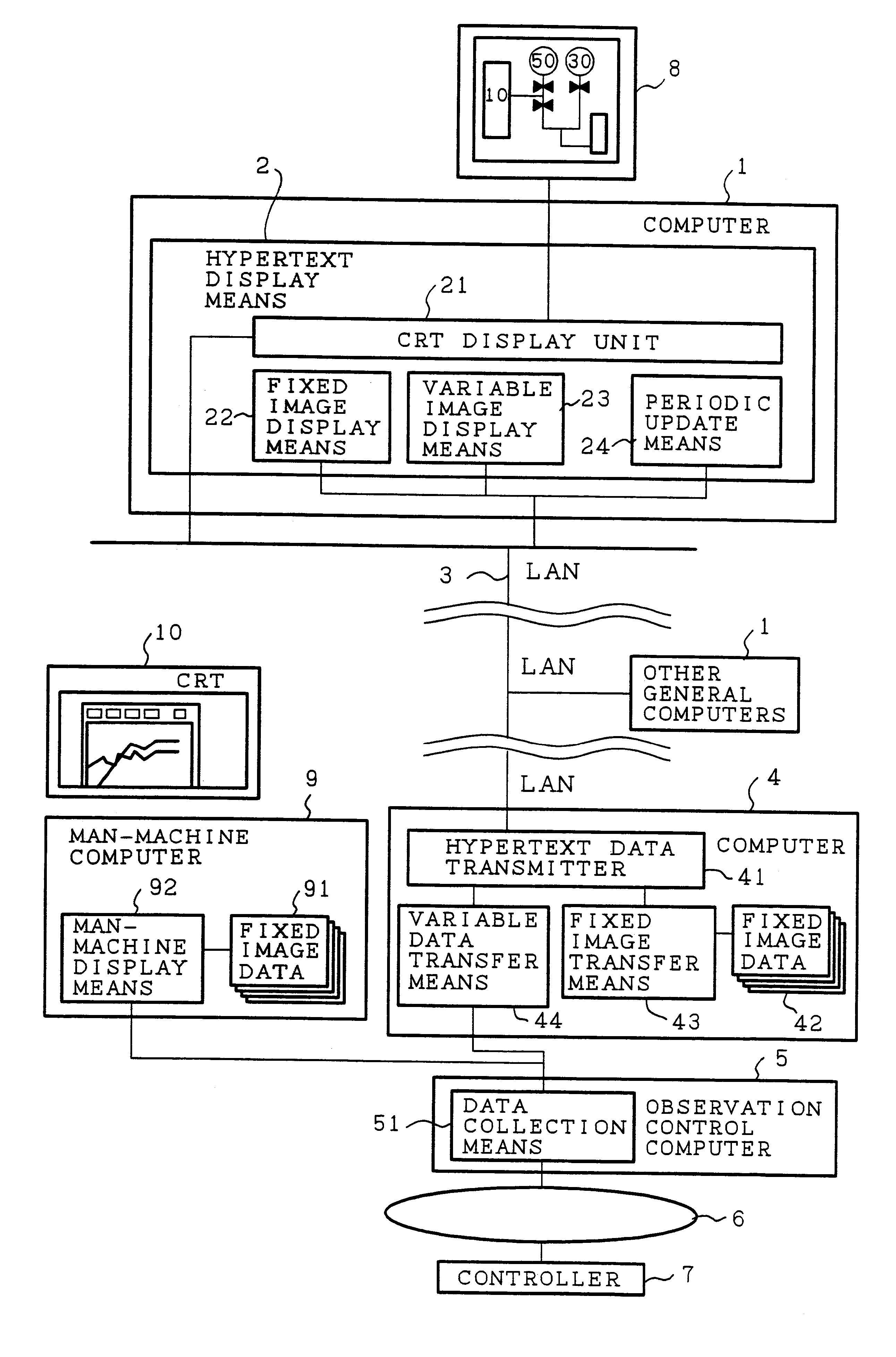
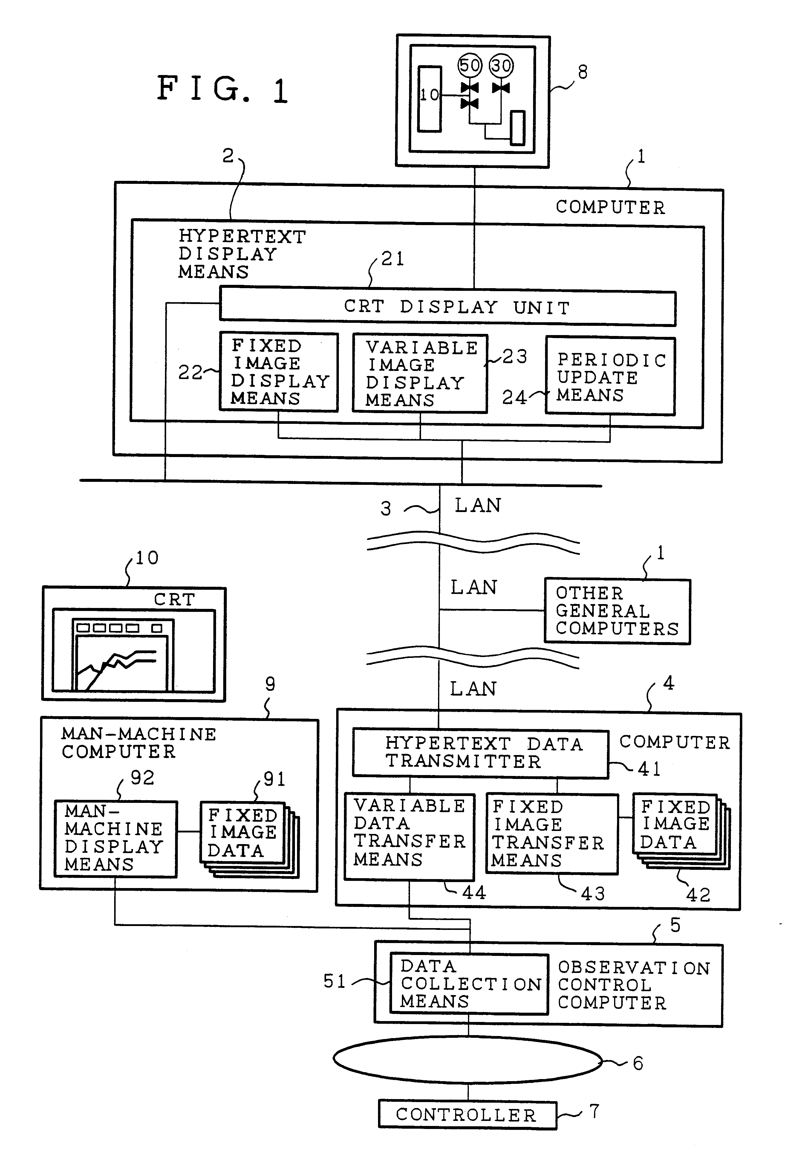
FIG. 4 is a block diagram showing an embodiment 2 of the remote observation system in accordance with the present invention, in which the same portions as those of FIG. 1 are designated by the same reference numerals, and the duplicate explanation thereof are omitted here. In this figure, the reference numeral 45 designates image acquisition means including a program with a function of the fixed image display means, a program with a function of the variable image display means and a program with a function of the periodic update means. The reference numeral 25 designates a program storage which is provided at the office side for storing the programs sent from the observation object side to carry out the data display.

The operation will now be described.

FIG. 5 is a flowchart illustrating the operation. When an operator selects the observation image on the hypertext display means 2 at step ST51, the hypertext data transmitter 41 transmits, on the hypertext, the corresponding program, t...


PUM


Abstract

An remote observation system including a hypertext data transmitter for transmitting hypertext data from an observation object side to an office side through a data transmission line connecting therebetween, and a hypertext display unit for displaying at the office side the hypertext data sent from the observation object side. The hypertext data consist of a combination of fixed image data representing a plant in its entirety and status data of various portions of the plant, which are collected by a data collection device. This makes it possible to solve a problem of a conventional remote observation system in that only insufficient information is acquired at the office side because the office side is not directly connected with the observation object side, and hence the office side can acquire the information on the states of the observation object side only when the observation object side sends reports to the office side.

Description

1. Field of the InventionThe present invention relates to a remote observation system for observing the state of a plant from a distant place.2. Description of Related ArtFIG. 6 shows a configuration of a conventional remote observation system. In this figure, the reference numeral 101 designates a computer such as a PC (personal computer) or a workstation placed in an office faraway from the observation object. The computer 101 includes a hypertext display unit 102 for displaying a hypertext.The reference numeral 103 designates a network such as LAN (Local Area Network) for connecting the computer 101 with other computers; 104 designates a plurality of computers like engineering workstations for communicating with the computer 101 through the network 103; and 105 designates a CRT for displaying data transmitted from the hypertext display unit 102. These devices 101-105 are placed at the office side.The reference numeral 106 designates a controller for carrying out control and data ...

Claims


Application Information

Patent Timeline
Patent Type & Authority Patents(United States)
IPC IPC(8): G06F15/16H04B3/00H04B3/46H04Q9/00G05B19/042G05B23/02
CPCG05B19/0428G05B23/0272G05B2219/24048G05B2219/34038
Inventor TANABE, JIRO
Owner MITSUBISHI ELECTRIC CORP
Why Eureka
Try Eureka