Systems and methods for infering hail and lightning using an airborne weather radar volumetric buffer

a weather radar and volumetric buffer technology, applied in meteorology, climate sustainability, instruments, etc., can solve the problems of unsatisfactory calibration, limited weather reflectivity and turbulence display functions, and the radar displayed reflectivity is not necessarily well calibrated

Active Publication Date: 2012-02-07
HONEYWELL INT INC
View PDF6 Cites 60 Cited by
  • Summary
  • Abstract
  • Description
  • Claims
  • Application Information

AI Technical Summary

Problems solved by technology

These first radars displayed reflectivity only in grayscale and were not necessarily well calibrated.
While these have all been significant improvements, the weather reflectivity and turbulence display functions have some limitations with respect to the desired goal of presenting to the crew a direct indication of hazards.
Conversely, there are weather hazards that are not associated with reflectivity or turbulence levels that airborne weather radar can detect, most notably clear turbulence (often due to nonprecipitation air mass boundaries or mountain-induced activity) and also including icing conditions.

Method used


Image

  • Systems and methods for infering hail and lightning using an airborne weather radar volumetric buffer
  • Systems and methods for infering hail and lightning using an airborne weather radar volumetric buffer
  • Systems and methods for infering hail and lightning using an airborne weather radar volumetric buffer

Examples


Embodiment Construction

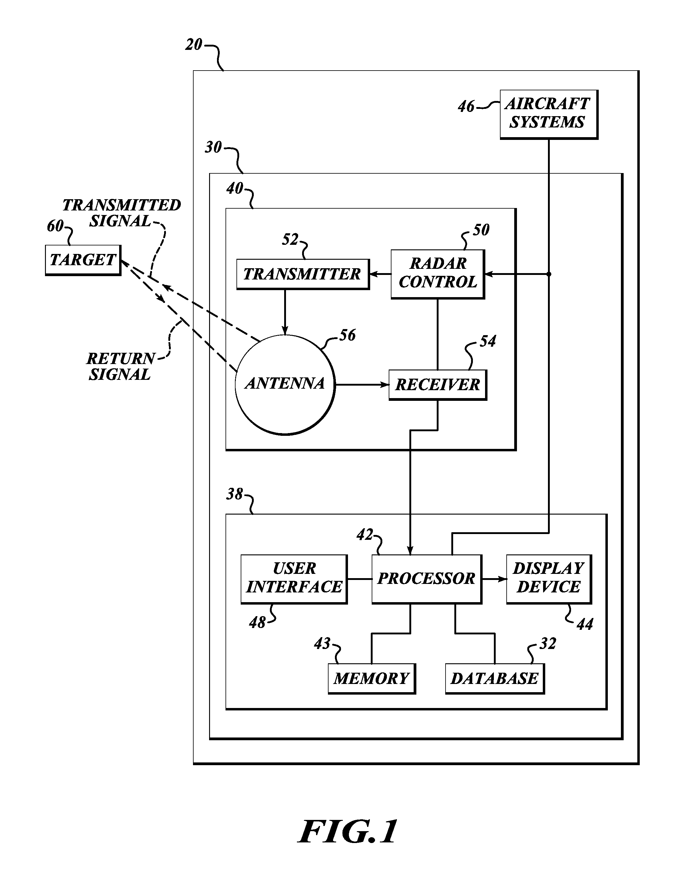
[0017]FIG. 1 illustrates an embodiment of a weather display system 30 for providing improved weather radar display functionality. The exemplary weather display system 30 includes a weather radar system 40 and a display / interface front-end 38, and receives information from an aircraft system 46. The display / interface front-end 38 includes a processor 42, memory 43, a display device 44, a user interface 48, and a database 32. An example of the radar system 40 includes a radar controller 50 (coupled to the user interface 48), a transmitter 52, a receiver 54, and an antenna 56. The radar controller 50 controls the transmitter 52 and the receiver 54 for performing the sending and receiving of signals through the antenna 56. The weather radar system 40 and the display / interface front-end 38 are electronically coupled to the aircraft system 46.

[0018]Radar relies on a transmission of a pulse of electromagnetic energy, referred to herein as a signal. The antenna 56 narrowly focuses the trans...


PUM


Abstract

A weather radar system for improving output of potential lightning and hail weather conditions. An exemplary system includes a processor that receives and stores the weather radar reflectivity values into a three-dimensional buffer, receives an outside air temperature value, and determines freezing level based on the received outside air temperature value. The processor generates lightning icon(s) when a reflectivity value stored at cell(s) of the three-dimensional buffer above determined freezing level is greater than a first threshold amount. Also, the processor adds 1.6 km to the determined freezing level and generates hail icon(s) when a reflectivity value stored at cell(s) at the determined freezing level plus 1.6 km are greater than a second threshold amount. The display device displays the hail and lightning icons when an altitude value that corresponds to the cells associated with the generated lightning icons has been selected for display.

Description

BACKGROUND OF THE INVENTION[0001]Since their introduction in the 1950s, airborne weather radar systems have primarily provided an indication of weather “reflectivity” in the field of view of the radar. Reflectivity is a radar parameter and is roughly correlated to rainfall rate. These first radars displayed reflectivity only in grayscale and were not necessarily well calibrated. However, in those early days, the ability to see where there was and wasn't rainfall was a great improvement to flying blind or making very conservative circumnavigations to avoid weather.[0002]As weather radar evolved, improvements in the accuracy of reflectivity measurements were made, along with improved display capability, first with the introduction of digital radar, which provided monochromatic but discrete levels of reflectivity indication. This was followed by the introduction of color displays allowing increasing reflectivity levels to be displayed as green, yellow, and red.[0003]In the 1980s severa...

Claims


Application Information

Patent Timeline
Patent Type & Authority Patents(United States)
IPC IPC(8): G01S13/95
CPCG01S13/953G01W1/10G01S7/20G01S7/22Y02A90/10
Inventor BUNCH, BRIAN PAULCHRISTIANSON, PAUL
Owner HONEYWELL INT INC
Why Eureka
Try Eureka