Displacement elements for a clip machine

a technology of disassembly and clip machine, which is applied in the direction of sausage twisting/linking machines, butchering, sausage filling/stuffing machines, etc., can solve the problems of inability to exclude, inability to exclude and inability to prevent damage to the packaging casing. , to achieve the effect of preventing damage to the packaging casing or pinching, minimizing damage to the tubular packaging, and reducing the cost of production

Active Publication Date: 2012-02-14
POLY CLIP SYST
View PDF14 Cites 7 Cited by
  • Summary
  • Abstract
  • Description
  • Claims
  • Application Information

AI Technical Summary

Benefits of technology

[0008]Such a reinforcement or thickened portion provides for closing the gap produced by the reduction in length of the first shorter displacer shear of the second pair of displacer shears between the second displacer shears, which have been moved together, of the two pairs of displacer shears. That thus effectively prevents the packaging casing from being damaged or pinched.
[0009]In that respect it is advantageous if a gap is formed between the radially outwardly facing surface of the first displacer shear of the second pair of displacer shears and the surface which faces theretowards of the reinforcement. That prevents the end of the shorter displacer shear, that faces away from the pivot point, from colliding with the reinforcement. As a result the shortened displacer shear can bear over the full surface area involved against the first displacer shear of the first pair of displacer shears.
[0010]To make the constriction procedure even more reliable and to further minimize damage to the tubular packaging the dimension of the gap must be reduced to a minimum. In order nonetheless to ensure that the pairs of displacer shears move together reliably and without collision it is further advantageous if the gap is oriented at an acute angle to the axis of the plaited portion.

Problems solved by technology

Those previously known clip machines however suffer from disadvantages.
Thus it is not possible to exclude the possibility that the shortened displacer shear, particularly when the products in sausage form are of large diameters and / or when dealing with delicate packaging casings, penetrates into the packaging casing during the constriction procedure and thus form a fold which can no longer be engaged by the closure clip.
It is also not possible to exclude damage to the packaging casing.

Method used


Image

  • Displacement elements for a clip machine
  • Displacement elements for a clip machine
  • Displacement elements for a clip machine

Examples


Embodiment Construction

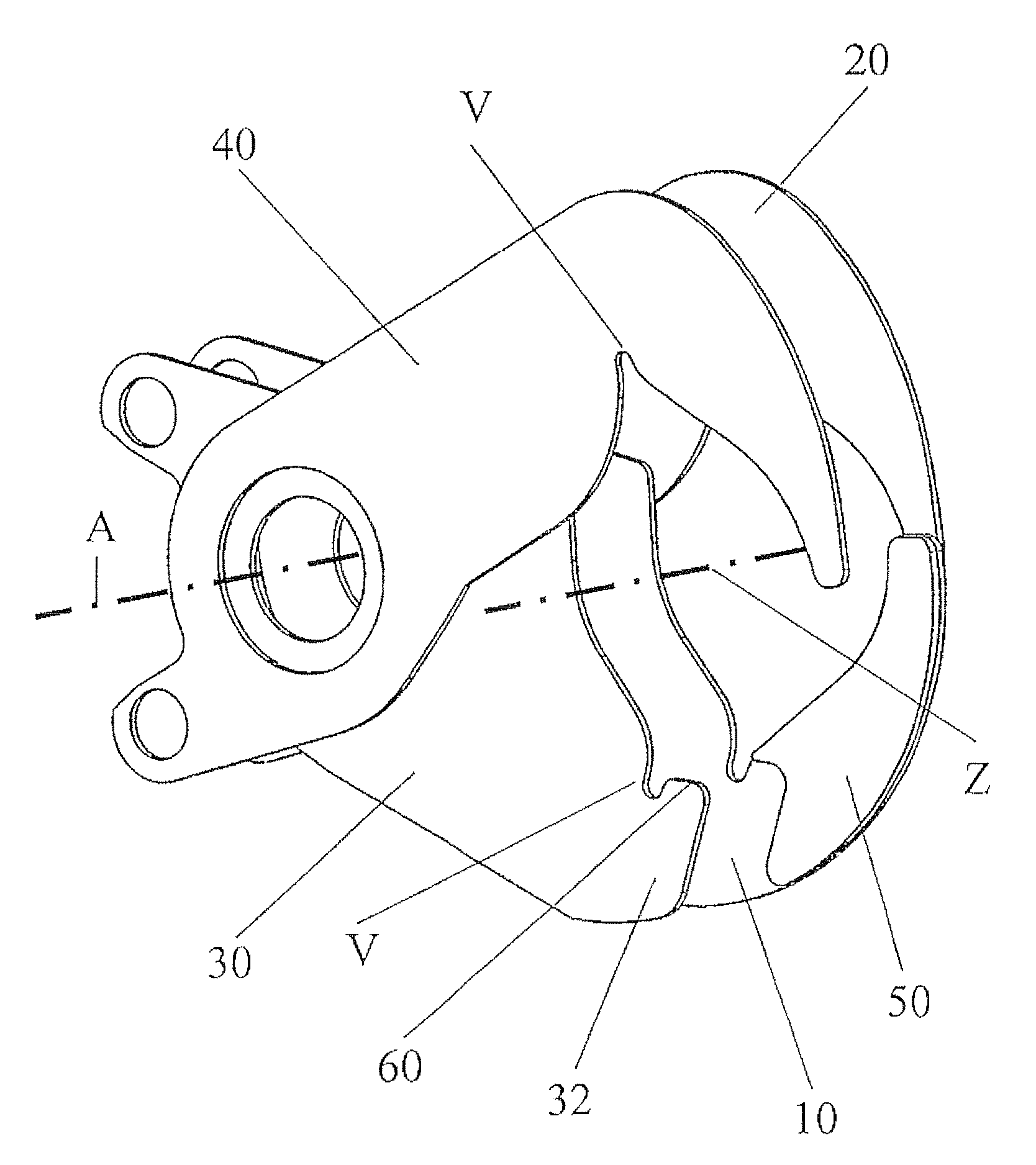
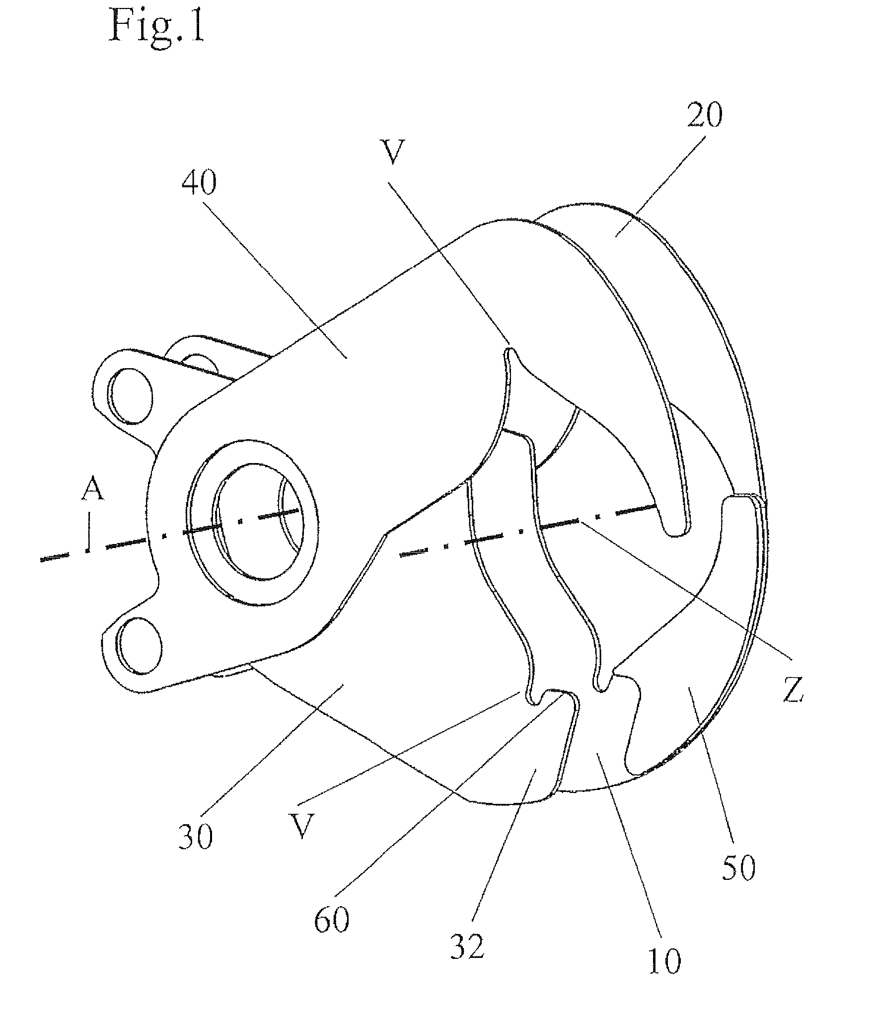
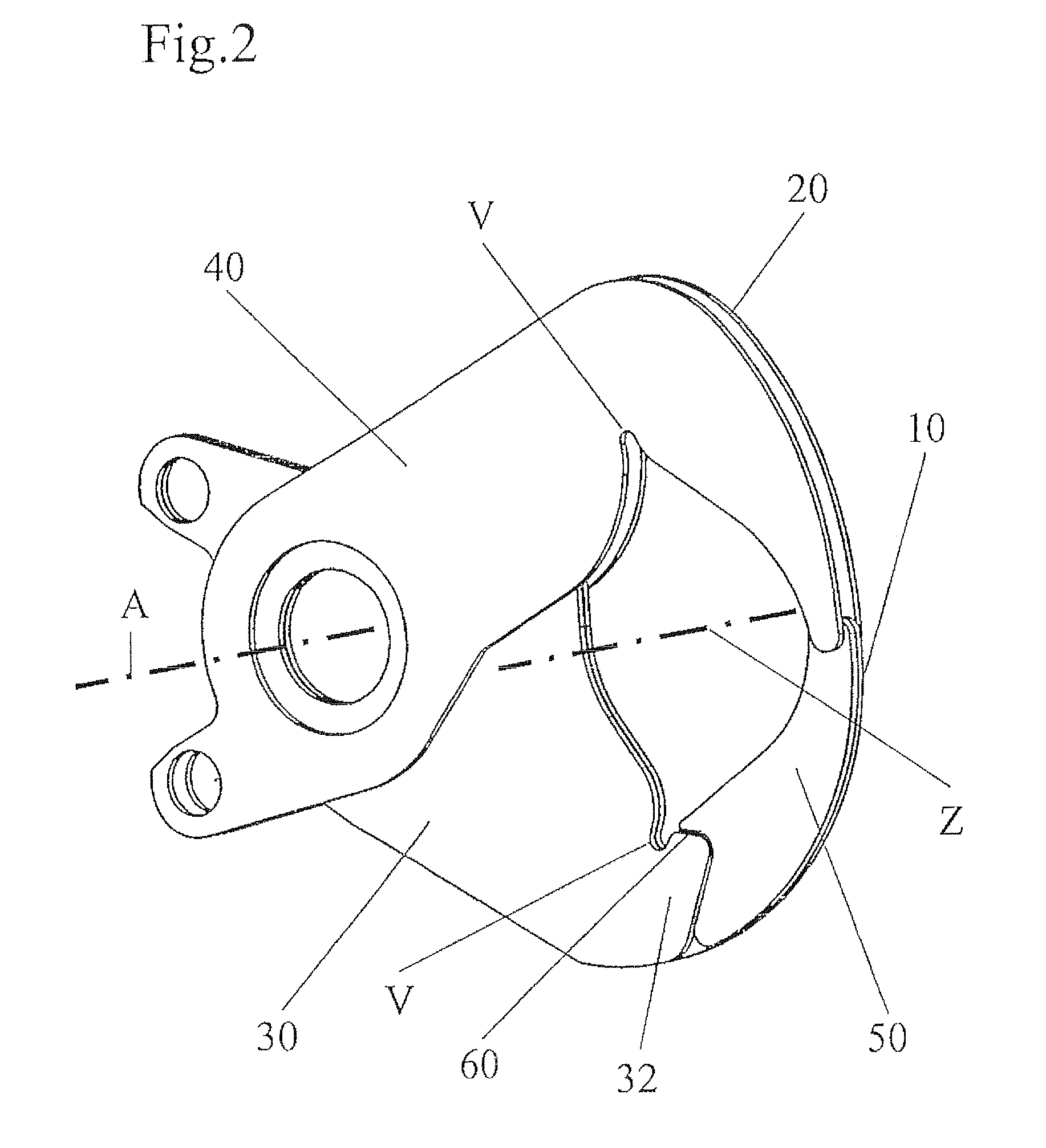
[0016]Referring to FIG. 1 the displacer assembly according to the invention has a first pair of displacer shears 10, 20 and a second pair of displacer shears 30, 40 which are oriented in mutually parallel relationship and are arranged reversibly pivotably towards each other about a common axis A. To produce the reversible pivotal movement of the displacer shears 10, 20, 30, 40 there is provided a drive (not shown in FIG. 1) engaging the ends of the displacer shears 10, 20, 30, 40, which face towards the left from the pivot axis A. The respective first displacer shears 10, 30 and the second displacer shears 20, 40 of the pairs of displacer shears 10, 20, 30, 40 are disposed in this case in at least approximately coincident mutually juxtaposed relationship. The ends of the displacer shears, that face from the common pivot axis A in the direction of the plaited portion axis Z are angled in a hook shape in such a way that the ends of the first and second displacer shears 10, 30 and 20, ...


PUM


Abstract

A displacer assembly for a clip machine, in particular a sausage clip machine, including at least a first pair of displacer shears and a second pair of displacer shears arranged parallel thereto. The displacer shears are arranged pivotably about a common axis and are reversibly movable towards each other for constriction of the filled packaging casing for forming a filling material-free plaited portion. In that respect the first pair of displacer shears comprises two displacer shears which are at least approximately identical in minor image relationship and the second pair of displacer shears has a second displacer shear which is at least approximately identical to the displacer shears of the first pair of displacer shears, as well as a first, shorter displacer shear. The first displacer shear of the first pair of displacer shears has a reinforcement which at least approximately reproduces the contour of the part, which is cut off for shortening purposes, of the first displacer shear of the second pair of displacer shears.

Description

BACKGROUND OF THE INVENTION[0001]The invention concerns a displacer assembly for a clip machine, in particular a sausage clip machine. In particular the invention concerns a displacer assembly for a clip machine, in particular a sausage clip machine, which includes: at least a first pair of displacer shears and a second pair of displacer shears arranged parallel thereto, wherein the displacer shears are reversibly movable towards each other to constrict the filled packaging casing to form a filling material-free plaited end portion. In that case the first pair of displacer shears comprises two displacer shears which are at least approximately identical in minor image relationship. The second pair of displacer shears has a first displacer shear which is at least approximately identical to the displacer shears of the first pair of displacer shears and a second shorter displacer shear.[0002]A clip machine of the kind set forth hereinbefore, which is known for example from German patent...

Claims


Application Information

Patent Timeline
Patent Type & Authority Patents(United States)
IPC IPC(8): A22C11/00A22C11/10
CPCA22C11/105
Inventor REITZ, JURGENWALDSTADT, MANFRED
Owner POLY CLIP SYST
Why Eureka
Try Eureka