Airborne basestation

a basestation and airborne technology, applied in the field of airborne basestations, can solve the problems of limited communication range of operation, limited system capacity, and high deployment and maintenance costs of land-based wireless infrastructures

Inactive Publication Date: 2012-02-14
THE UNITED STATES OF AMERICA AS REPRESENTED BY THE SECRETARY OF THE NAVY
View PDF13 Cites 95 Cited by
  • Summary
  • Abstract
  • Description
  • Claims
  • Application Information

AI Technical Summary

Benefits of technology

[0020]Embodiments of the present invention provide robust systems that combine the benefits of providing the network switching capability in the air with the benefits of using an affordable airborne platform instead of costly sate...

Problems solved by technology

However, the communication range of operation is limited.
Also, land-based wireless infrastructures are expensive to deploy and maintain, especially in remote areas.
Thus, the number of base stations limits the potential capacity of system 10 for processing calls to and from wireless terminals.
Present wireless communication systems fail to provide broadband wireless communication in real time across extended distances while maintaining a LOS path between stations where one or both stations may be in motion.
Many regions of the world today have a sparse or no fixed communication infrastructure and lack the resources needed to upgrade their existing equipment to match more developed areas.
However, present wireless systems fail to meet the needs of specific applications.
Because of inherent limitations in the transmission media, wireless communication must compensate for noise introduced in the radio path.
However, all of these techniques affect the cost and complexity of a wireless system.
Moreover, compensating for unreliable wireless paths becomes increasingly difficult as the data rate increases.
Various satellite-based solutions have been proposed to address the above identified issues, but are generally too costly unless applied over continental or larger geographic areas.
Additionally, the often huge increase in wireless earth-space-earth path distance betw...

Method used


Image

  • Airborne basestation
  • Airborne basestation
  • Airborne basestation

Examples


Embodiment Construction

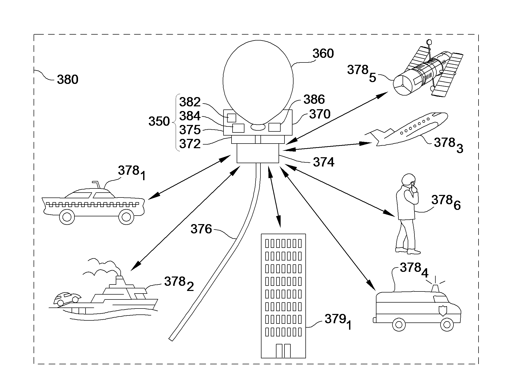
[0036]As will be better understood from the following description, embodiments of the present invention are directed to an airborne communication system for providing broadband, multi-user communication within a network. Broadband communication provides efficient communication of voice, video and data. It should be noted that the following description will discuss various embodiments and environments in which such embodiment are preferably operated. However, such discussion is provided by way of example and not by way of limitation.

[0037]With reference to FIG. 3, a system 350 in accordance with an embodiment of the present invention uses a lighter-than-air vehicle 360 to provide relay broadband communication service among mobile units 378i or non-mobile units 379i in a coverage area or cell 380. The mobile units 378i can be ground vehicles such as illustrated by car 3781 or ambulance 3784, or water vehicles as illustrated by boat 3782, or air vehicles as illustrated by fixed-wing ai...


PUM


Abstract

A wireless communications basestation that utilizes a light weight high directivity electronically-steerable antenna mounted on a lighter-than-air vehicle to providing relay broadband communication service among mobile units in a geographic area is provided. The lighter-than-air vehicle carries aloft the antenna; a radio and a switching device for routing. A gateway may also be provided to enable communications with a wide area network. A communication system for a geographic area utilizing the airborne wireless communications basestation is also presented. The system includes a number of user equipment units located in the geographic area in communication with the airborne wireless communications basestation. The user equipment units may utilize omni-directional antennas for low data rate communications, and/or a high directivity antenna.

Description

FEDERALLY-SPONSORED RESEARCH AND DEVELOPMENT[0001]This invention (Navy Case No. 98,720) is assigned to the United States Government and is available for licensing for commercial purposes. Licensing and technical inquires may be directed to the Office of Research and Technical Applications, Space and Naval Warfare Systems Center, Pacific, Code 72120, San Diego, Calif. 92152; voice (619) 553-2778; email T2@spawar.navy.mil.CROSS-REFERENCE TO RELATED APPLICATION[0002]The present application is related to pending patent application entitled Steerable Antenna, Ser. No. 11 / 603,707, filed Nov. 22, 2006, the teachings and disclosure of which are hereby incorporated in their entireties by reference thereto.BACKGROUND OF THE INVENTION[0003]This invention relates generally to methods and apparatuses for communicating broadband signals between multiple customers and, more particularly, to methods and apparatuses for communicating using a low-cost, easily maintainable, fast deployable communicati...

Claims


Application Information

Patent Timeline
IPC IPC(8): H04W4/00
CPCH04W16/28H04W84/06H04B7/18502
Inventor OLSEN, RANDALL
Owner THE UNITED STATES OF AMERICA AS REPRESENTED BY THE SECRETARY OF THE NAVY
Why Eureka
Try Eureka