
Fitting for trimming a horizontal stabilizer of an aircraft

a technology for aircraft and stabilizers, applied in aircrafts, fuselages, transportation and packaging, etc., can solve the problems of high manufacturing cost, difficult and costly manufacturing of such stabilizers, and high manufacturing costs

Active Publication Date: 2012-02-21
AIRBUS OPERATIONS SL
View PDF20 Cites 1 Cited by
  • Summary
  • Abstract
  • Description
  • Claims
  • Application Information

AI Technical Summary

Benefits of technology

The present invention relates to a fitting made of composite material, a carbon-fibre reinforced plastic, for the spindle of a motor / spindle unit in an aircraft. The fitting is designed to allow for trimming of the horizontal stabilizer of the aircraft while still meeting fail-safe requirements. The fitting includes a torsion box with two side walls that are joined to the tail fuselage of the aircraft. The fitting also includes a primary fastening element and a secondary fastening element to ensure safety. The primary fastening element is made of the torsion box side walls and two end elements that are joined to the side walls. The secondary fastening element is a central element with an I-shaped cross section. The fitting is easy and cheap to manufacture and is less heavy than metal designs.

Problems solved by technology

In spite of the trends in recent years to introduce the use of composite materials or “composites” such as CFRP (Carbon Fibre Reinforced Plastic) in as many components of an aircraft as possible owing to the saving in weight implied by this material compared to aluminium (the metal material which is most used), the majority of aircraft manufacturers are reluctant to use carbon fibre for fittings since the complexity of these fittings leads to an expensive manufacturing.
This complexity is particularly pronounced in the case of the fitting of the motor / spindle unit for trimming a horizontal stabilizer of an aircraft, due to the relatively large number of lugs which it must have and the arrangement of said lugs.
The problem posed by the fitting of the motor / spindle unit for a horizontal stabilizer according to US 2008 / 0001029 A1 is that it has a very complex geometrical form, in particular as regards its central element, so that manufacturing thereof is difficult and costly, requiring moreover additional parts in order to stabilize the fitting and achieve an adequate behaviour in response to a load.

Method used


Image

  • Fitting for trimming a horizontal stabilizer of an aircraft
  • Fitting for trimming a horizontal stabilizer of an aircraft
  • Fitting for trimming a horizontal stabilizer of an aircraft

Examples

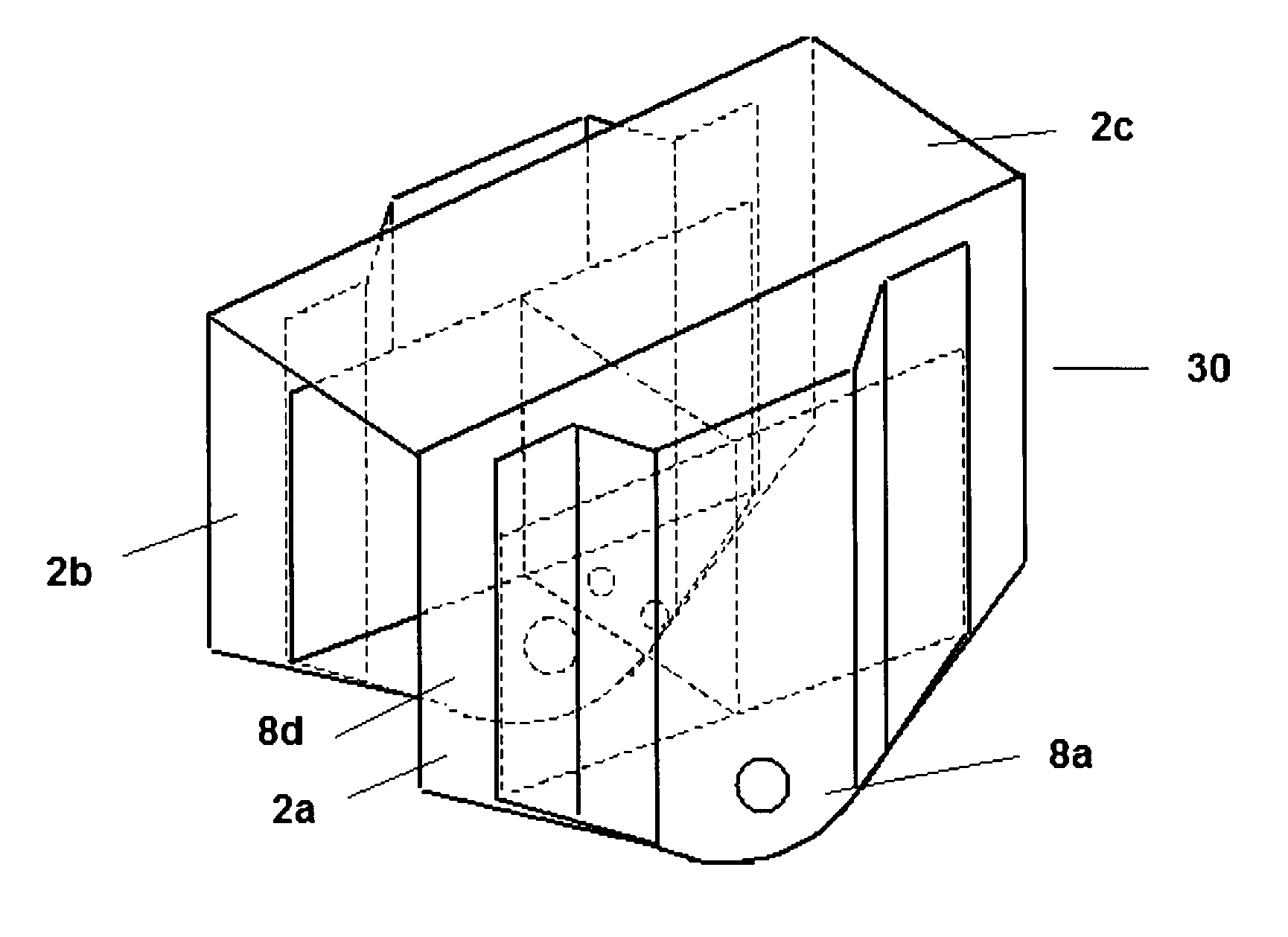

Embodiment Construction

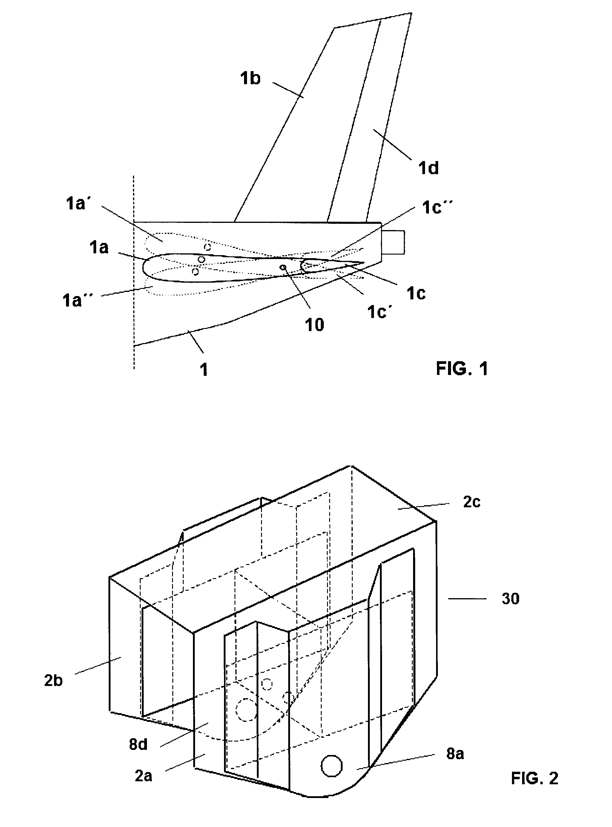
[0028]FIG. 1 shows the tail fuselage 1 of an aircraft, on which a horizontal stabilizer 1a with its elevator 1c as well as a vertical stabilizer 1b with its rudder 1d are arranged. The horizontal stabilizer 1a can be trimmed in a conventional manner by means of a motor / spindle mechanism which is connected to a control point 10, actuation of which causes the horizontal stabilizer 1a to pivot so that, also in a conventional manner, the horizontal stabilizer 1a and the elevator 1c are able to adopt the positions 1a′, 1c′ and 1a″, 1c″, respectively, as shown in the said FIG. 1.

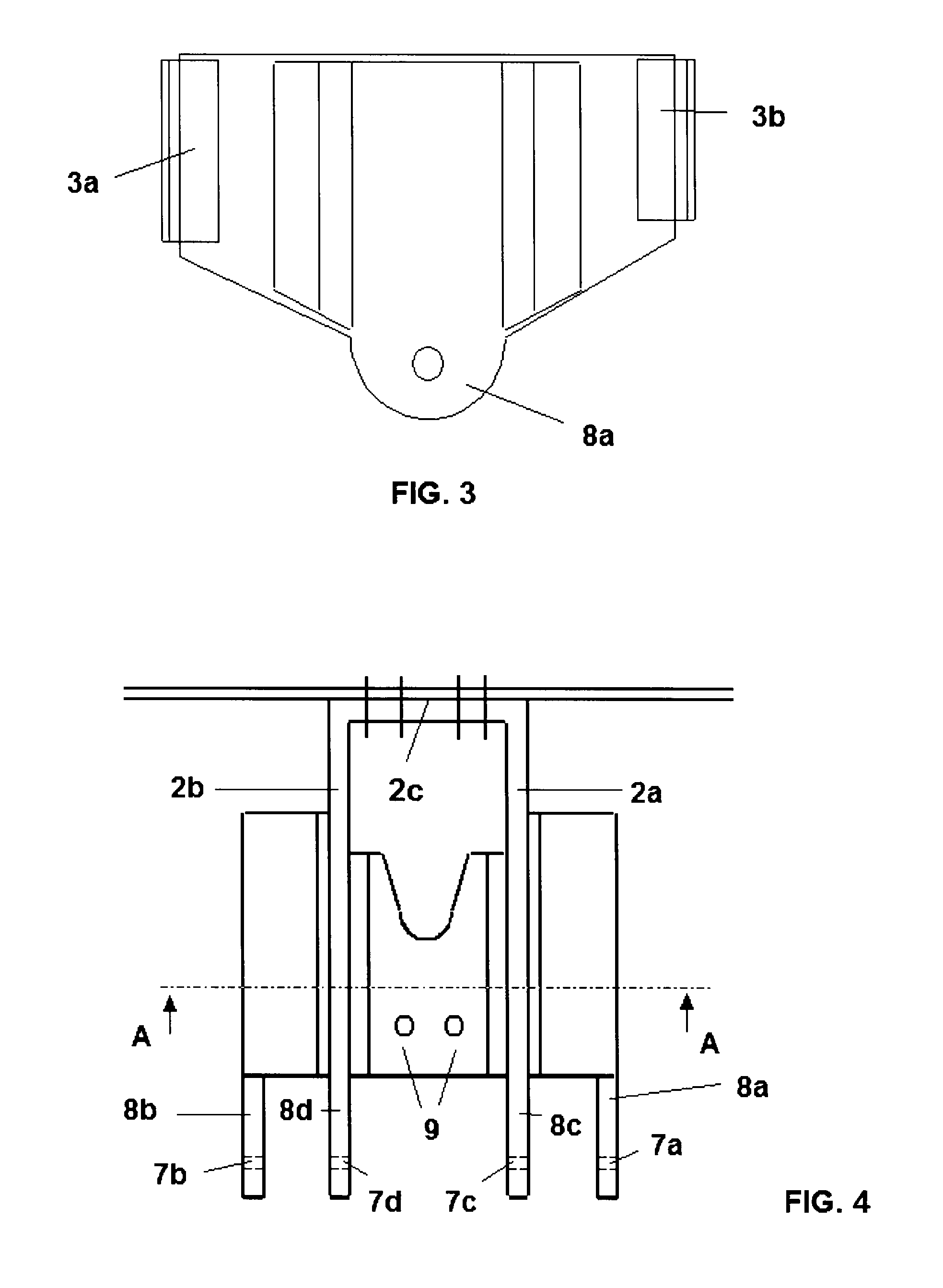
[0029]FIGS. 2 to 6 show a preferred embodiment of the fitting 30 according to the invention for trimming a horizontal stabilizer 1a, said fitting 30 comprising the side walls 2a and 2b of a torsion box. Said fitting 30 comprises first joining means 3a in the form of angle pieces so that the walls 2a and 2b can be riveted to a first frame (not shown in the figures) of the tail fuselage 1 of the aircraft. The fittin...


PUM


Abstract

A fitting for trimming the horizontal stabilizer of an aircraft, made of composite material, the fitting including side walls of a torsion box as well as joining elements which join the fitting to the frames of the tail fuselage of the aircraft, the side walls being joined together by a central element which includes a first end part joined to the first side wall of the fitting, a second end part joined to the second side wall of the fitting and a central part which joins together the end parts, the fitting includes end elements which are joined to the side walls on their outer face, the fitting having, owing to its greater rigidity in response to side load and vertical load stresses which tend to close the side walls, its greater integration and the simplicity of the load path, an optimum structural behavior in response to the aircraft stresses.

Description

FIELD OF THE INVENTION[0001]The present invention relates to a fitting for trimming a horizontal stabilizer of an aircraft.PRIOR ART[0002]Usually the assembly of a trimmable horizontal stabilizer in an aircraft is performed by coupling the said stabilizer to the aircraft by means of one or two pivoting points and a control point. To allow trimming of the plane in which the horizontal stabilizer is situated, the control point must be able to change its position vertically so as to allow the stabilizer to pivot on the pivoting point or points. In order to allow the said change in position of the control point, it is usual to provide a motor / spindle unit fixed by means of a fitting so that rotation of the said spindle in one direction or the other causes the upward or downward movement of the control point.[0003]The fitting which fixes the spindle of the above motor / spindle unit is a metal fitting which is usually joined to a torsion box, said torsion box in turn being joined to two lo...

Claims


Application Information

Patent Timeline
Patent Type & Authority Patents(United States)
IPC IPC(8): B64C1/06
CPCB64C5/02B64C1/26
Inventor RODRIGUEZ, ELENA AREVALO
Owner AIRBUS OPERATIONS SL
Learn More