
Mobile medical imaging system and methods

a mobile medical imaging and mobile technology, applied in the field of medical imaging, can solve the problems of limiting the practical application of diagnostic imaging beyond the scope of diagnostic imaging, difficult to move these devices throughout the hospital, and immovable or exceedingly difficult to transport, so as to facilitate the transportation and/or storage of the device, and facilitate the effect of mobile medical imaging

Active Publication Date: 2012-02-21
MOBIUS IMAGING
View PDF24 Cites 119 Cited by
  • Summary
  • Abstract
  • Description
  • Claims
  • Application Information

AI Technical Summary

Benefits of technology

The present invention is a mobile medical imaging device that can be easily transported and attached to multiple support structures. The device includes an imaging gantry that can translate, rotate, and tilt with respect to a support base, allowing for imaging in multiple orientations. The device can be used in applications such as x-ray computed tomography and magnetic resonance imaging. The invention also includes a tabletop support for supporting an object to be imaged, which can be detachable from the base and interchanged with other tabletop supports. The gantry ring has a relatively large imaging bore and can rotate between an imaging position and a transport position to facilitate easy transport of the system. The invention also includes methods of imaging an object using the imaging system.

Problems solved by technology

Conventional computed tomography (CT) and magnetic resonance (MR) imaging devices, are typically either immovable or exceedingly difficult to transport and consist of multiple components including the imaging gantry and a separate imaging table.
It is difficult to move these devices throughout a hospital because they have not been designed to fit though standard hallways and the imaging table top is unusable or unfit for procedures other than standard diagnostic imaging or do not allow imaging with the patient in a sitting position.
In addition, a separate single procedure specific table top is generally indexed to translate into and out of the imaging device throughout a procedure thus limiting its practical applications beyond diagnostic imaging.
The difficulties of moving such a device throughout a hospital or office are multiplied when the device needs to be moved from one floor to another.
Further, it is not an uncommon experience to realize that the device cannot pass through the doorway without its widening.
Further, the devices cannot readily be moved from spot to spot once inside a room.

Method used


Image

  • Mobile medical imaging system and methods
  • Mobile medical imaging system and methods
  • Mobile medical imaging system and methods

Examples


Embodiment Construction

[0032]This application claims the benefit of U.S. Provisional Application No. 61 / 142,494, filed Jan. 5, 2009, the entire teachings of which are incorporated herein by reference.

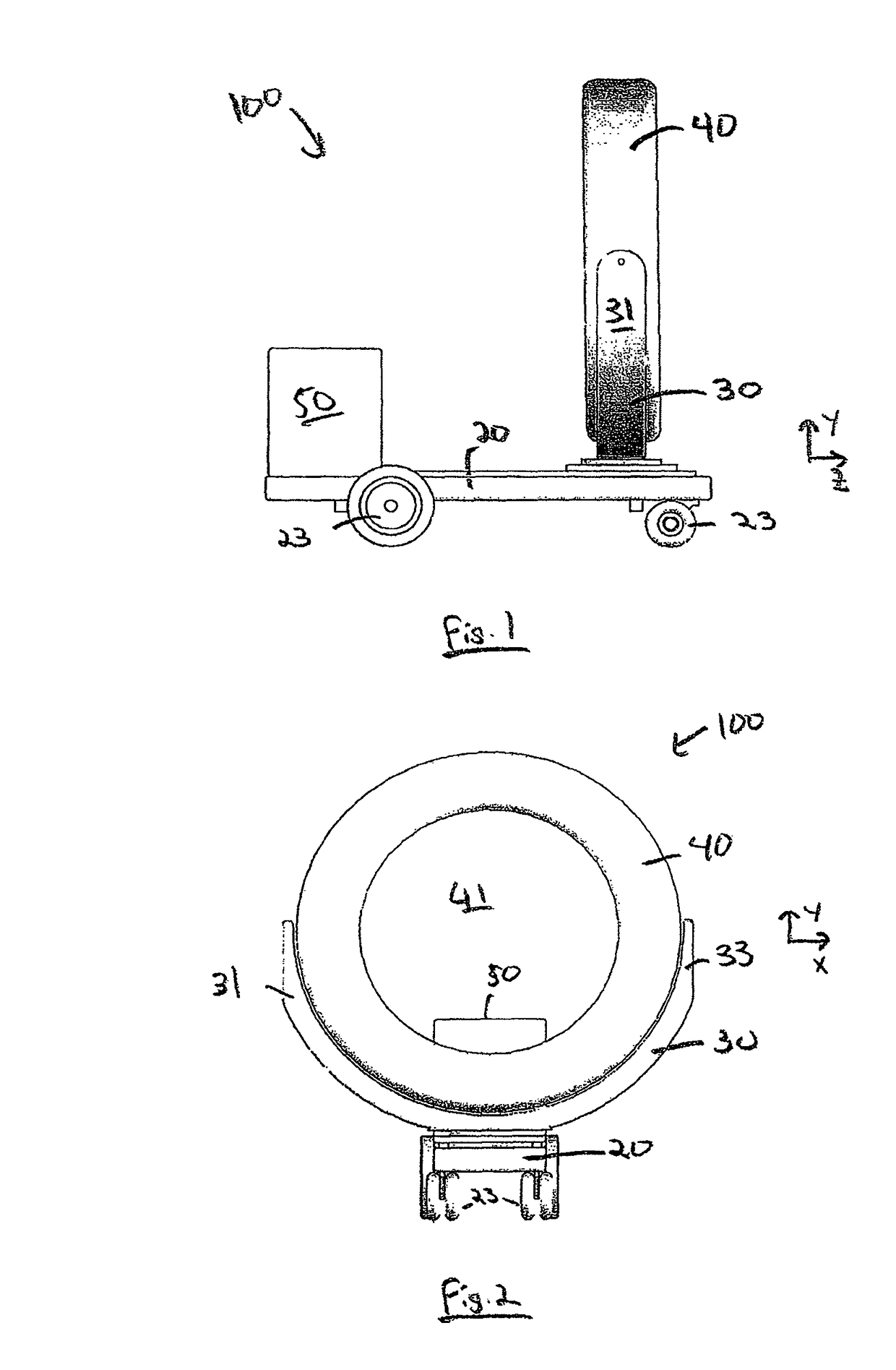
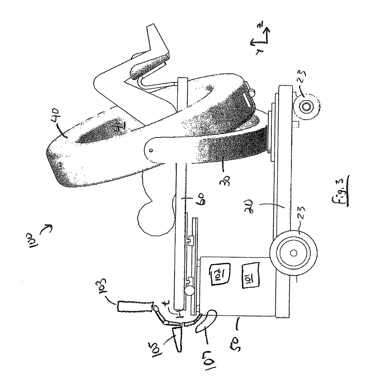
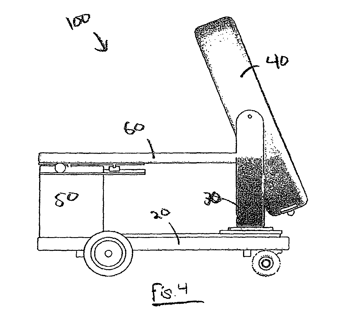
[0033]Referring to FIGS. 1-7, a mobile imaging system 100 according to one embodiment of the invention includes a mobile base 20, a gimbal support 30, a gantry ring 40, and a pedestal 50. FIGS. 1 and 2 are side and front views, respectively, of the mobile medical imaging system 100. The system 100 includes image collection devices, such as a rotatable x-ray source and detector array or stationary magnetic resonance imaging components, that are housed within the gantry ring 40. The system 100 is configured to collect imaging data, such as, for example x-ray computed tomography (CT) or magnetic resonance imaging (MRI) data, from an object located within the bore 41 of the gantry ring 40, in any manner known in the medical imaging field. As shown in FIG. 3, the pedestal 50 is adapted to support a tabletop suppor...


PUM


Abstract

A mobile medical imaging device that allows for multiple support structures, such as a tabletop or a seat, to be attached, and in which the imaging gantry is indexed to the patient by translating up and down the patient axis. In one embodiment, the imaging gantry can translate, rotate and / or tilt with respect to a support base, enabling imaging in multiple orientations, and can also rotate in-line with the support base to facilitate easy transport and / or storage of the device. The imaging device can be used in, for example, x-ray computed tomography (CT) and / or magnetic resonance imaging (MRI) applications.

Description

CROSS-REFERENCE TO RELATED APPLICATION[0001]This application claims the benefit of U.S. Provisional Application No. 61 / 142,494, filed Jan. 5, 2009.STATEMENT REGARDING FEDERALLY SPONSORED RESEARCH OR DEVELOPMENT[0002]N / ABACKGROUND OF THE INVENTION[0003]The present invention is in the technical field of medical imaging, including, for example, mobile computed tomography and magnetic resonance imaging devices.[0004]Conventional computed tomography (CT) and magnetic resonance (MR) imaging devices, are typically either immovable or exceedingly difficult to transport and consist of multiple components including the imaging gantry and a separate imaging table. It is difficult to move these devices throughout a hospital because they have not been designed to fit though standard hallways and the imaging table top is unusable or unfit for procedures other than standard diagnostic imaging or do not allow imaging with the patient in a sitting position. In addition, a separate single procedure s...

Claims


Application Information

Patent Timeline
Patent Type & Authority Patents(United States)
IPC IPC(8): H05G1/02
CPCA61B5/0555A61B6/032A61B6/04A61B6/0478A61B6/4411A61B6/548A61B6/4405A61B6/508A61B6/4447A61B5/055A61B5/704A61B6/0407
Inventor GREGERSON, EUGENE A.
Owner MOBIUS IMAGING
Learn More