
Interlaced video field motion detection

a video field and interlaced technology, applied in the field of television signal processing, can solve the problems of motion not being properly detected at all, time difference between fields in interlaced television signal, and particular difficulties in consistently switching between operating regimes

Inactive Publication Date: 2012-02-21
TAMIRAS PER PTE LTD LLC
View PDF114 Cites 4 Cited by
  • Summary
  • Abstract
  • Description
  • Claims
  • Application Information

AI Technical Summary

Benefits of technology

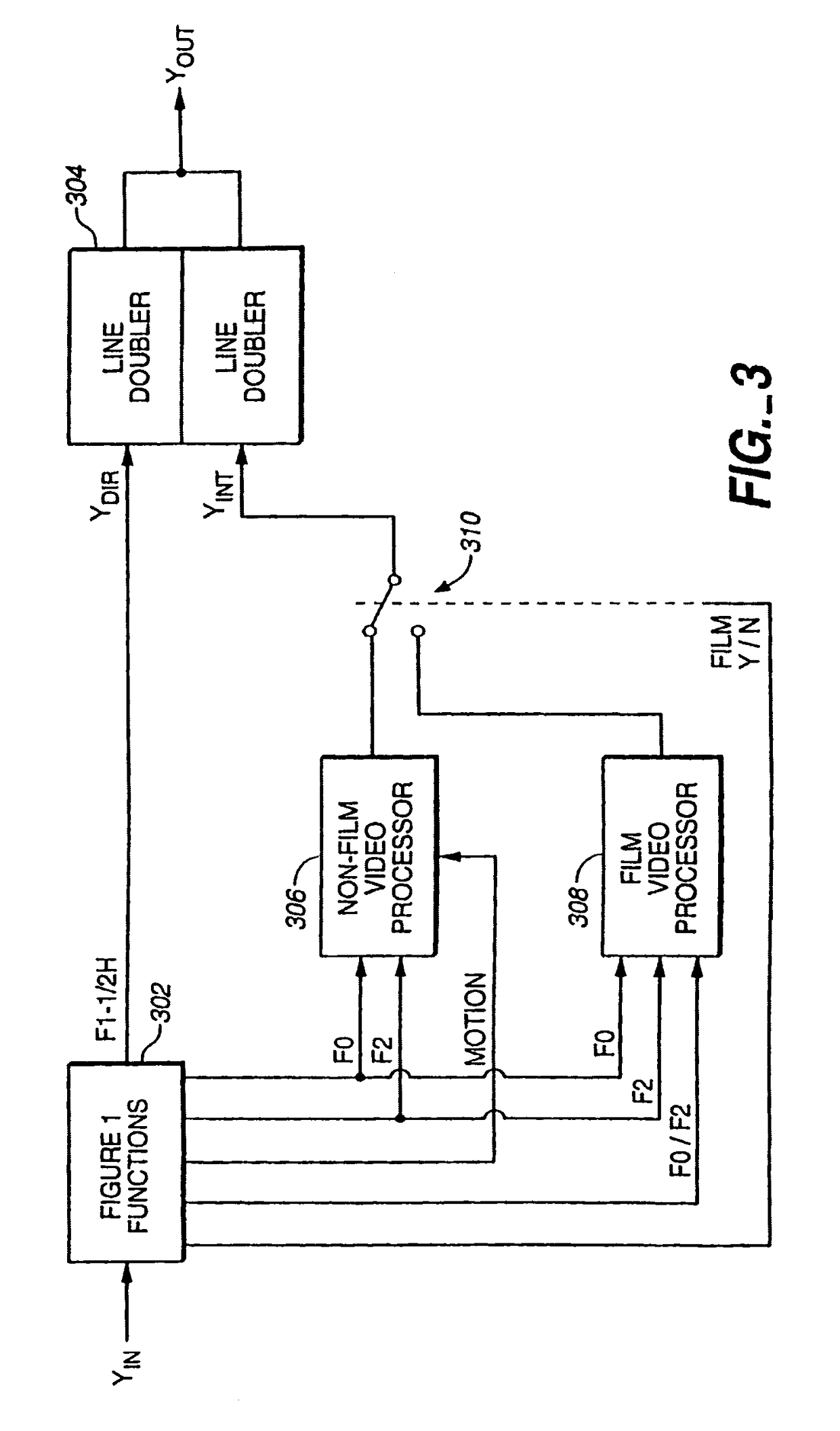
"The present invention relates to improved signal processing apparatus and methods for detecting motion picture film sources in television signals. The technical effects of the invention include improved detection of motion picture film sources, particularly in television standards converters and video information compressors, by using scan line or intra-field interpolation in regions of the television picture display in which movement is occurring. The invention also addresses the problem of a sawtooth effect resulting from field merging in line doublers and proposes an improved technique for providing intra-field interpolation in areas of the picture having motion."

Problems solved by technology

One problem resulting from field merging is that there is a time difference between fields in the interlaced television signal.
A potential problem with switchable inter-field / intra-field interpolation line doublers is that motion may not be properly detected at all times, thus allowing the above mentioned jagged vertical or diagonal transition artifacts to appear briefly and intermittently.
Such arrangements may have particular difficulty in consistently switching correctly between operating regimes when operating on an interlaced television signal that has been subject to data compression or standards conversion (as from PAL to NTSC, for example).
However, the motion picture film detection arrangement is also subject to problems.
For example, a video edit (rather than a film edit) may disrupt the 3-2 pulldown ratio, causing merged television fields to be derived from different film frames.
Although the undesired effect is fleeting, it is perceptible to the eye, occasionally disturbing an otherwise near perfect line doubling arrangement.
The last discussed problem may also arise in the motion picture film source line doubling arrangement when the input interlaced television signal fades from a film source to a video source.
During those few fields before changeover from the film mode of operation, the same sort of ragged sawtooth artifacts may be generated if there is motion between the fields.
In addition, the problem may also arise when the interlaced television signal derived from a motion picture source has been imperfectly data compressed or standards converted.

Method used


Image

  • Interlaced video field motion detection
  • Interlaced video field motion detection
  • Interlaced video field motion detection

Examples


Embodiment Construction

[0032]Except as noted herein, practical embodiments of the invention may be implemented using analog, digital (including digital signal processing with software), or hybrid analog / digital techniques. The equivalency of analog and digital implementations in most contexts is well known to those of ordinary skill in the art.

[0033]Throughout this document, for simplicity, signal inputs and outputs are drawn as single points and signal carrying lines are drawn as single lines, It wilt be understood that, in practice, more than one input or output point and more than one signal carrying line may be required, depending on the format of the signals and the manner in which the practical embodiments of the invention are physically constructed.

[0034]It should also be understood that functions shown separately may be combined with others in whole or in part. In addition, those of ordinary skill in the art will understand that, in practice, switches shown throughout the various figures will be i...


PUM


Abstract

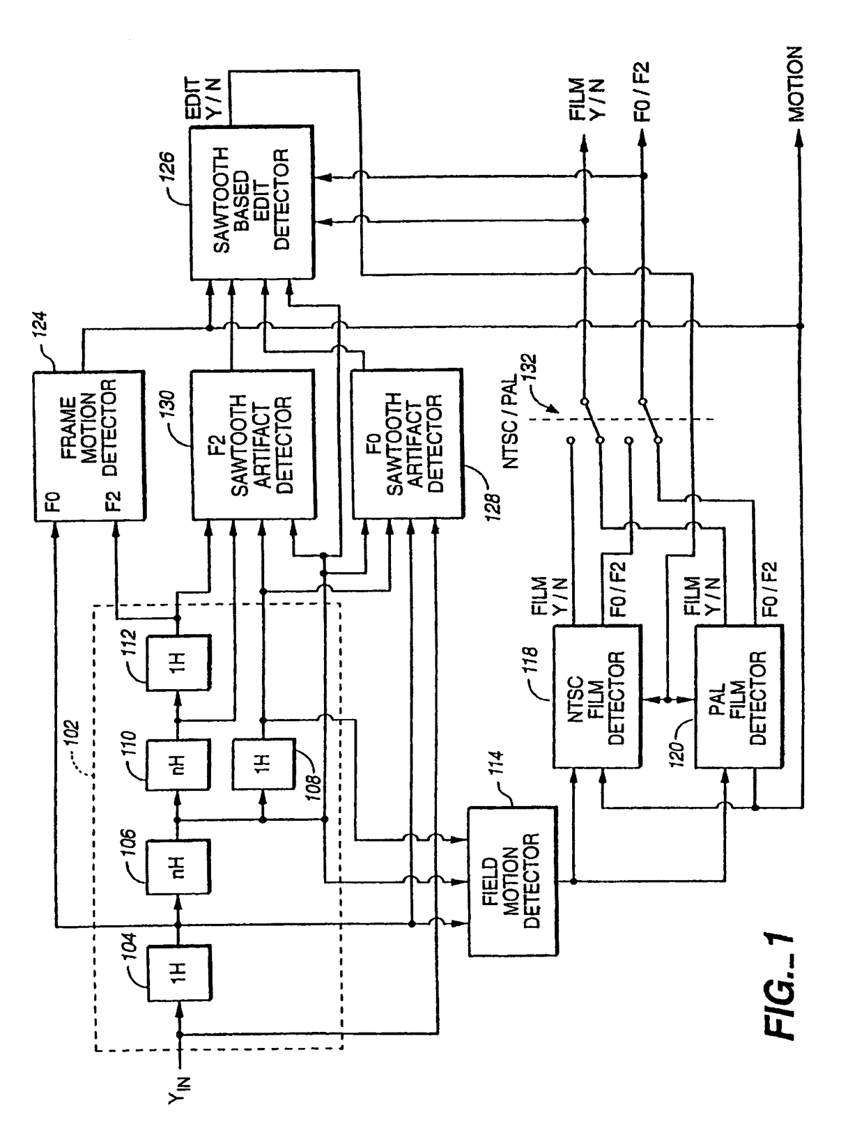
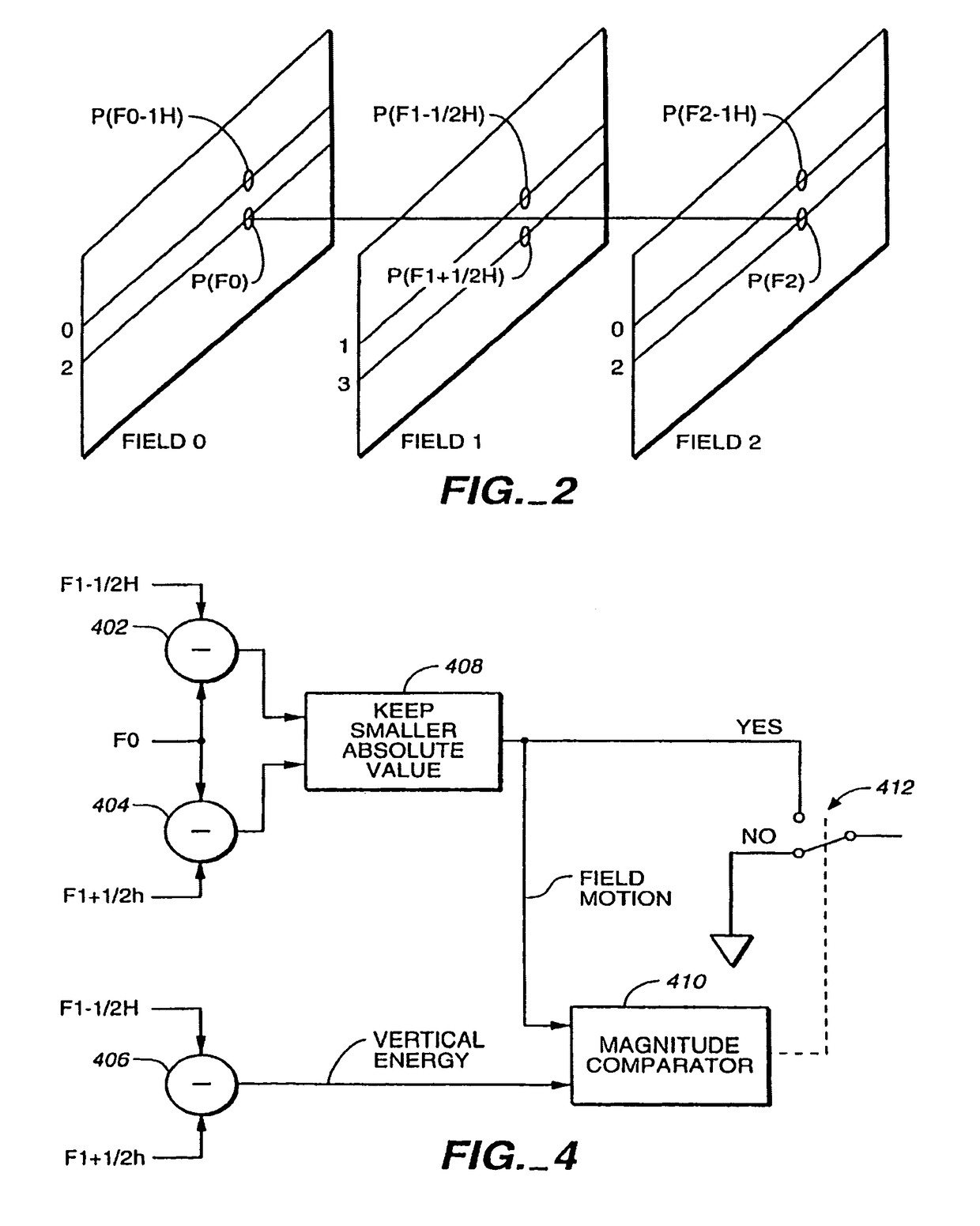
A television line doubler (interlaced to progressive scan converter) incorporating the following aspects an improved field motion detector which does not treat low frequency vertical transitions as motion; a frame motion detector having an improved ability to differentiate motion from subcarrier signal components; a sawtooth artifact detector; a sawtooth artifact detector in combination with a film pattern detector, such that the artifact detector can take the film pattern detector out of film mode earlier than it would if it only were responsive to a break in the film pattern; tandem field motion detectors; an improved field based film detector; film pattern detectors and motion detectors used therewith which operate by performing end-of-field calculations; the combination of a field motion detector and a frame motion detector such that the frame motion detector provides a motion signal used as a verification by the field motion detector; an improved NTSC film detector requiring a minimum number of NTSC film pattern sequences; and an improved PAL film detector employing a minimum motion threshold detector.

Description

CROSS-REFERENCES TO RELATED APPLICATIONS[0001]This application is a continuation application and claims priority to U.S. patent application Ser. No. 10 / 999,395, filed Nov. 29, 2004; which is a divisional of U.S. patent application Ser. No. 10 / 388,686, filed Mar. 14, 2003, now U.S. Pat. No. 6,859,237, entitled “Film source video detection,” issued Feb. 22, 2005; which is a divisional of U.S. patent application Ser. No. 09 / 780,057, filed Feb. 9, 2001, now U.S. Pat. No. 6,580,463, entitled “Film source video detection,” issued Jun. 17, 2003; which is a divisional of U.S. patent application Ser. No. 09 / 440,678, filed Nov. 16, 1999, now U.S. Pat. No. 6,201,577, entitled “Film source video detection,” issued Mar. 13, 2001; which is a divisional of U.S. patent application Ser. No. 08 / 948,841, filed Oct. 10, 1997, now U.S. Pat. No. 6,014,182, entitled “Film source video detection,” issued Jan. 11, 2000, all of which are hereby incorporated by reference.FIELD OF THE INVENTION[0002]The presen...

Claims


Application Information

Patent Timeline
Patent Type & Authority Patents(United States)
IPC IPC(8): H04N5/14H04N5/44H04N7/00H04N7/01
CPCH04N7/0115H04N7/012
Inventor SWARTZ, PETER D
Owner TAMIRAS PER PTE LTD LLC
Learn More