Fixing structure of wire harness

a technology of fixing structure and wire harness, which is applied in the direction of roofs, cables, insulated conductors, etc., can solve the problems of hard aging of fixing force and hard falling of wire harness, and achieve the effect of preventing the generation of flapping sound (noise) of wire harness and preventing the wire harness from falling

Active Publication Date: 2012-02-28
TOYOTA BOSHOKU KK
View PDF9 Cites 5 Cited by
  • Summary
  • Abstract
  • Description
  • Claims
  • Application Information

AI Technical Summary

Benefits of technology

[0007]Such fixing structure conducts fixing by the latching piece formed by cutting the acoustical material, being contributive to cost reduction since not using tapes or clips, and thus can prevent generation of VOC since not needing an adhesive. In addition, aging of the fixing force is hard to occur, making the wire harness hard-to-fall. Moreover, the latching piece is formed by cutting the acoustical material and can therefore be formed in any positions. For example, multiple latching pieces can be arranged in a row along the path of the wire harness, so as to prevent flapping of the wire harness caused by vibration, and thereby preventing or suppressing the generation of flapping sound (noise). Additionally, the cutting operation is simple in comparison with the attaching operation using tapes and clips, and the workload can therefore be reduced.
[0008]In the fixing structure according to the present invention, the latching piece comprises a pair of protruding pieces and a section between protruding pieces positioned between the pair of protruding pieces, and the wire harness is held and latched between the protruding piece and the section between protruding pieces, so that the protruding piece prevents the vehicle interior material or the body disposed inside of the vehicle interior material from coming into contact with the wire harness.
[0009]As mentioned, when latching the wire harness between the pair of protruding pieces and the section between protruding pieces in a manner so as to hold the same, the wire harness can be surely latched by the pair of protruding pieces, and moreover, the wire harness can be prevented from coming into contact with the vehicle interior material or a vehicle body disposed inside of the vehicle interior material.
[0011]In this case, the two piece-shaped cut parts constitute the pair of protruding pieces, and the wire harness can be inserted into the cut open part between the protruding piece and the section between protruding pieces so as be latched by the latching piece without falling off, and moreover, can be prevented from coming into contact with, for example, the vehicle body disposed in one side of the vehicle interior material.
[0013]The power transmission line for electrical components mounted in the package tray is preferred to be latched in the back surface side of the package tray as a vehicle interior material, however, according to the present invention, the latching piece is provided in the acoustical material fixed to the back surface of the package tray so as to latch the wire harness thereto, and the wire harness can therefore be prevented from falling off the package tray, while the flapping of the wire harness is prevented, and thus, the generation of flapping sound (noise) of the wire harness can be prevented.
[0014]According to the present invention, there can be provided a hard-to-fall fixing structure of wire harness contributive to cost reduction in which VOC is not generated and flapping sound (noise) of wire harness is hard to occur.

Problems solved by technology

In addition, aging of the fixing force is hard to occur, making the wire harness hard-to-fall.

Method used


Image

  • Fixing structure of wire harness
  • Fixing structure of wire harness
  • Fixing structure of wire harness

Examples


Embodiment Construction

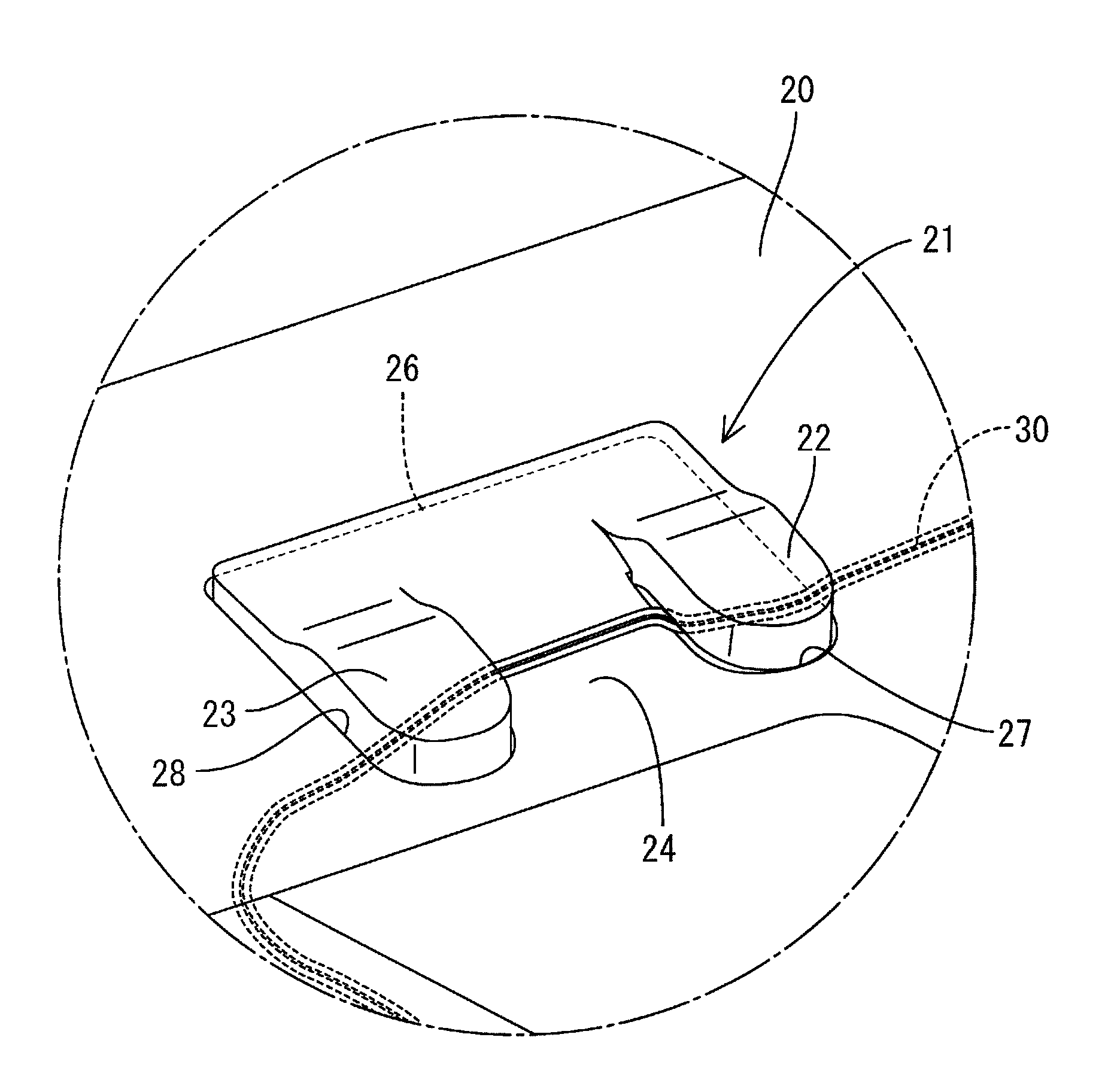
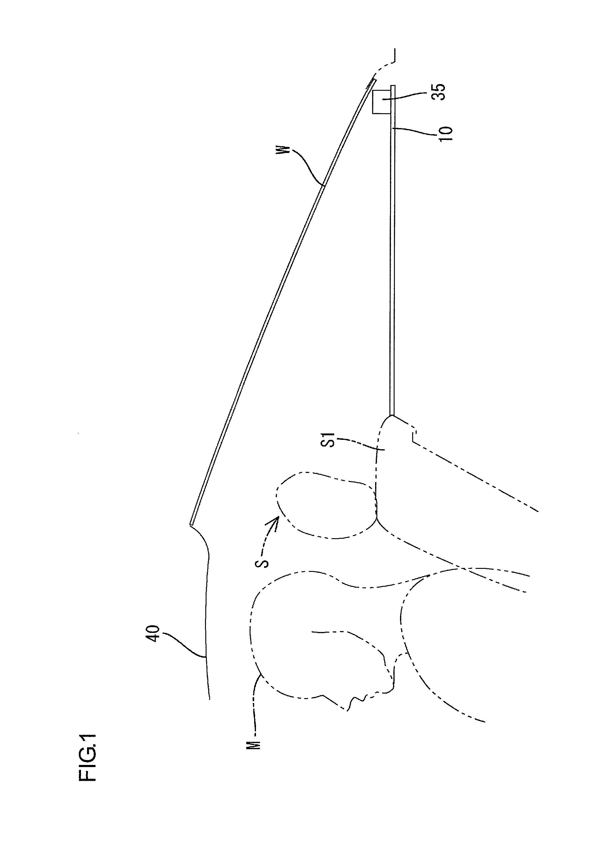
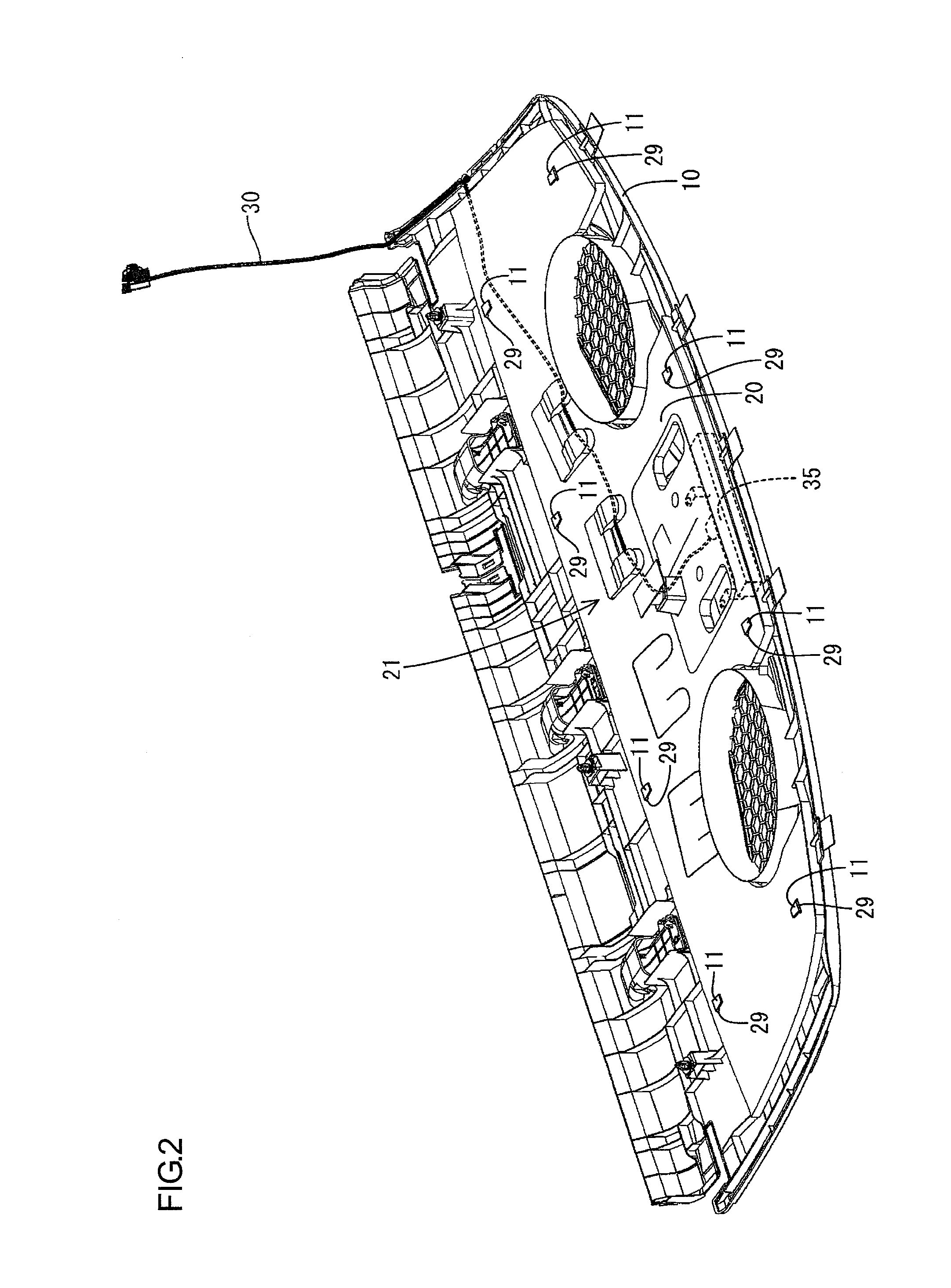
[0026]In what follows, as referring to the drawings, a fixing structure of wire harness according to the present invention is described. FIG. 1 is an explanatory view showing a schematic configuration of the rear part side surface of a vehicle; FIG. 2 is a perspective view showing the back surface configuration of a vehicle interior material (package tray) including the fixing structure of wire harness according to the present invention; FIG. 3 is an explanatory view showing the expanded fixing structure of wire harness; and FIG. 4 is a plane view showing arrangement positions of latching pieces the fixing structure of wire harness comprises.

[0027]In FIG. 1, arranged in the upper rear part of a sheet back S1 of a rear sheet S, in which a passenger M can be seated, is a package tray 10 as an interior material, and arranged in the package tray 10 is a high mount stop lamp 35 as an electrical component. On the other hand, in the lower part (inner part) of the package tray 10, as shown ...


PUM


Abstract

The present invention provides a hard-to-fall fixing structure of wire harness contributive to cost reduction in which VOC is not generated and flapping sound (noise) of wire harness is hard to occur. In the fixing structure of a wire harness to a vehicle interior material according to the present invention, a silencer pad (acoustical material) is fixed to the vehicle interior material, and the silencer pad is provided with a latching piece formed by cutting a portion of the present silencer pad, and the wire harness is latched to the latching piece.

Description

TECHNICAL FIELD[0001]The present invention relates to a fixing structure of wire harness.BACKGROUND ART[0002]Conventionally, as a fixing structure of wire harness to a vehicle interior material, fixing by means of an adhesive tape or a clip as disclosed in Patent literature 1 has been well-known. Patent literature 1 has been disclosing that a clip capable of elastic deformation which elastically latches wire harness is arranged in multiple positions to where the wire harness extends in a vehicle door trim as a vehicle interior material.[0003][Patent literature 1]: Japanese Unexamined Patent Publication No. H09-48295Problem to be Solved by the Invention[0004]According to the above-mentioned conventional fixing structure of wire harness by means of an adhesive tape or a clip, there have been problems as follows.(1) In the case of fixing by a tape, it is likely that separation due to aging degradation of the adhesion occurs, and thereby causing the wire harness to fall.(2) In the case ...

Claims


Application Information

Patent Timeline
Patent Type & Authority Patents(United States)
IPC IPC(8): F16L3/00
CPCB60R16/0215Y10T24/3924
Inventor YOSHIDA, KOJI
Owner TOYOTA BOSHOKU KK
Why Eureka
Try Eureka