Rolling bearing device

a technology of rolling bearings and sealing devices, which is applied in the direction of mechanical equipment, hubs, transportation and packaging, etc., can solve the problems of muddy water entering the inner ring and the outer ring of the bearing, and the cutting process requires gauging, so as to improve the sealing function and reduce the load of the sealing device of the rolling bearing. , the effect of improving the sealing function

Inactive Publication Date: 2012-02-28
JTEKT CORP
View PDF25 Cites 9 Cited by
  • Summary
  • Abstract
  • Description
  • Claims
  • Application Information

AI Technical Summary

Benefits of technology

[0005]An object of this invention is to provide a rolling bearing device in which a sealing member arranged in the clearance between a drive shaft and a knuckle is mounted on the side of a bearing thereby to make gauging process for the drive shaft and knuckle unnecessary and improve a muddy water invasion preventing function for the bearing side.

Problems solved by technology

Further, in the bearing used in such a wheel supporting device, muddy water will invade between its inner ring and outer ring.
In addition, these cuttings require gauging process owing to changes in the tolerances of the respective components.

Method used


Image

  • Rolling bearing device
  • Rolling bearing device
  • Rolling bearing device

Examples


Embodiment Construction

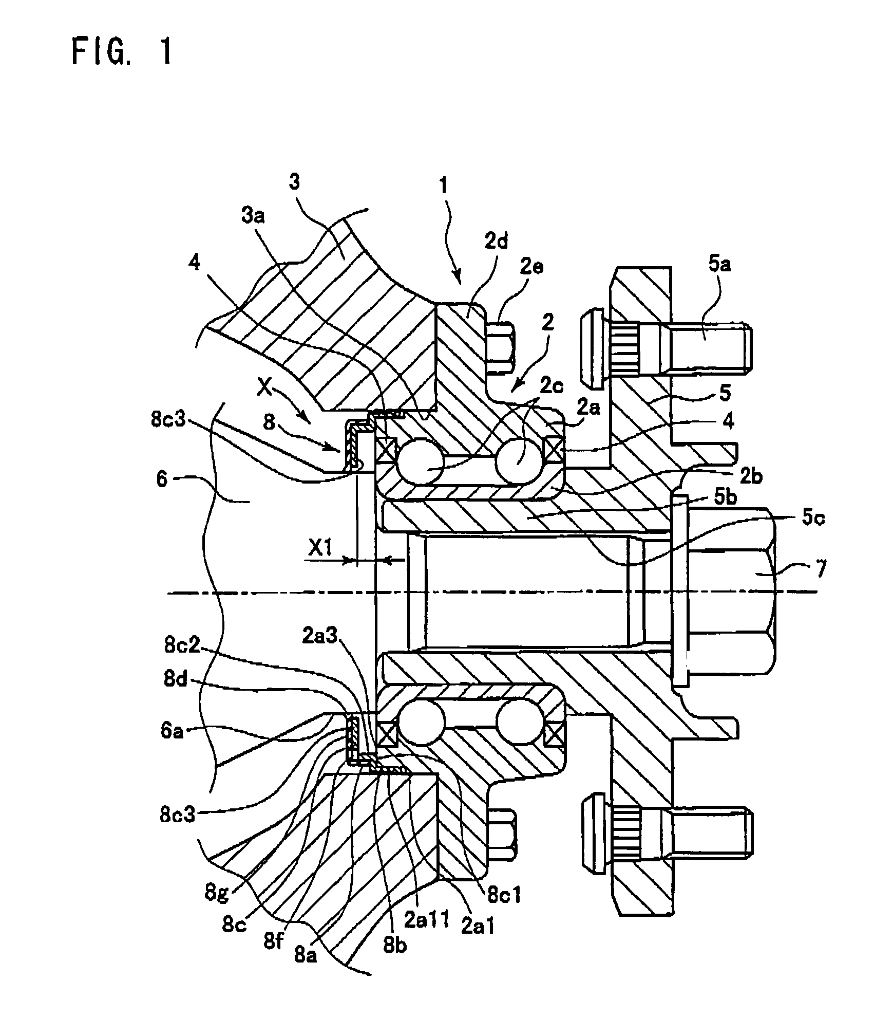
[0033]Hereinbelow, an explanation will be given of embodiments of this invention with reference to examples illustrated in the drawings. FIG. 1 is a sectional view of an example of a rolling bearing device according to this invention. Referring to FIG. 1, a rolling bearing device 1 includes a rolling bearing 2 having an outer ring 2a, an inner ring 2b and rolling elements 2c which are balls arranged in plural rows between the inner ring 2b and the outer ring 2a.

[0034]The rolling bearing 2 is connected to a mounting opening 3a of a knuckle 3 serving as a vehicle fixing member on a vehicle inner side. More specifically, the one side of the vehicle inner side in the outer ring 2a of the rolling bearing 2 is inserted and fitted into the mounting opening 3a and the flange 2d formed on the vehicle outer side in the outer ring 2a is fixed to the peripheral surface (vehicle outer side) of the mounting opening 3a of a knuckle 3 through a connecting member 2e such as a bolt / nut.

[0035]The rol...


PUM


Abstract

In a rolling bearing provided with an outer ring connected to a mounting opening of a knuckle, an inner ring connected to a wheel through a hub, a rolling element intervening between the outer ring and the inner ring and a sealing device for sealing the space between the inner and outer rings from the outside, the rolling bearing is provided with a sealing member for limiting the foreign substance invading the rolling bearing side from a clearance existing between a drive shaft provided rotatably with the inner ring and the knuckle, the sealing member including a ring-shaped cover including a cylinder press-fit in the outer ring and a ring-shaped upstanding wall extended radially inwardly from the cylinder and an outer lip provided at an inner diameter end of the ring-shaped upstanding wall, the outer lip serving to show the sealing function in cooperation with the drive shaft.

Description

BACKGROUND OF THE INVENTION[0001]This invention relates to a rolling bearing device used for a wheel supporting structure of a vehicle.[0002]There is a previously known wheel supporting device in a vehicle in a structure having a drive shaft rotating integrally with a wheel, the drive shaft connected with a hub for mounting the wheel and the hub rotatably supported by a knuckle through a bearing (see JP-A-2000-71710).[0003]Further, in the bearing used in such a wheel supporting device, muddy water will invade between its inner ring and outer ring. Thus, there is a known bearing device which prevents invasion of the muddy water by a sealing device provided between the inner and outer rings (see JP-A-2006-208038).[0004]However, in this bearing supporting device, as shown in FIG. 10, the muddy water will invade the sealing device C1 side of a bearing C from the clearance D located between an outer peripheral surface A1 of a drive shaft A and a mounting opening B1 for inserting the bear...

Claims


Application Information

Patent Timeline
Patent Type & Authority Patents(United States)
IPC IPC(8): F16C33/78B60B35/18F16C19/18
CPCB60B27/0005B60B27/0068B60B27/0073F16C19/184F16C33/7896F16C33/805F16C2326/02F16C33/7883F16C33/7886
Inventor MASUDA, YOSHINORI
Owner JTEKT CORP
Why Eureka
Try Eureka