Pipeline assembly comprising an anchoring device

a technology of pipeline and anchoring device, which is applied in the direction of pipe elements, pipe laying and repair, waterborne vessels, etc., can solve the problems of limiting the freedom of movement of the coupling point and reducing the movement in the touch-down zone, so as to reduce the movement of the pipeline

Inactive Publication Date: 2012-02-28
HEEREMA MARINE CONTRACTORS NEDERLAND SE
View PDF59 Cites 9 Cited by
  • Summary
  • Abstract
  • Description
  • Claims
  • Application Information

AI Technical Summary

Benefits of technology

[0026]a support device coupled to the pipeline at the delivery end. The connecting device limits the freedom of movement of the coupling point, thereby substantially reducing movements in the touch-down zone of the pipeline. Hence, fatigue of the pipeline, in particular in the touch-down zone, is substantially decreased.
[0098]The required form and position of the pipeline can be achieved by simply maneuvering the delivery end by the pipeline laying vessel. Hence, no complicated operations at the seabed are necessary.

Problems solved by technology

The connecting device limits the freedom of movement of the coupling point, thereby substantially reducing movements in the touch-down zone of the pipeline.

Method used


Image

  • Pipeline assembly comprising an anchoring device
  • Pipeline assembly comprising an anchoring device
  • Pipeline assembly comprising an anchoring device

Examples


Embodiment Construction

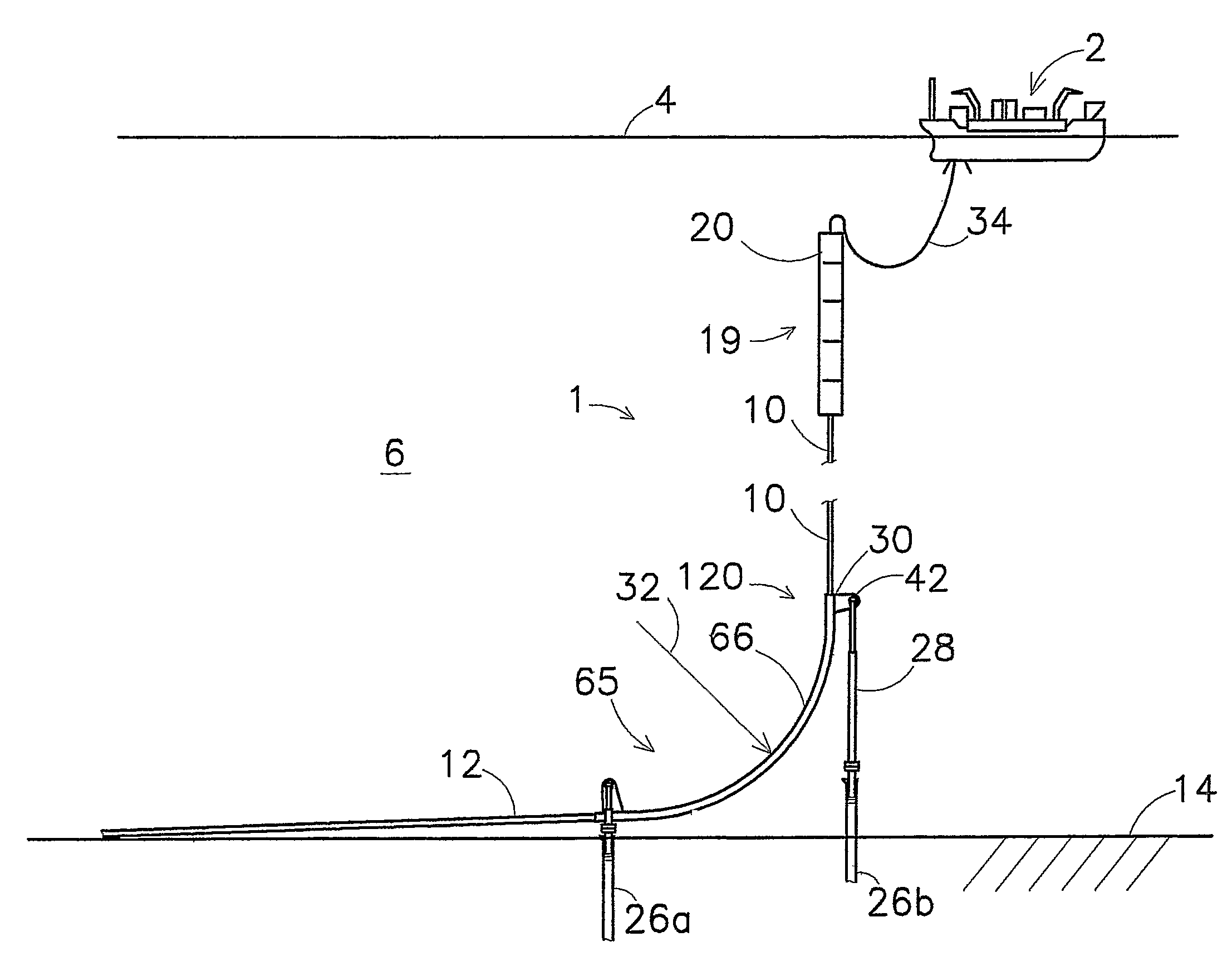
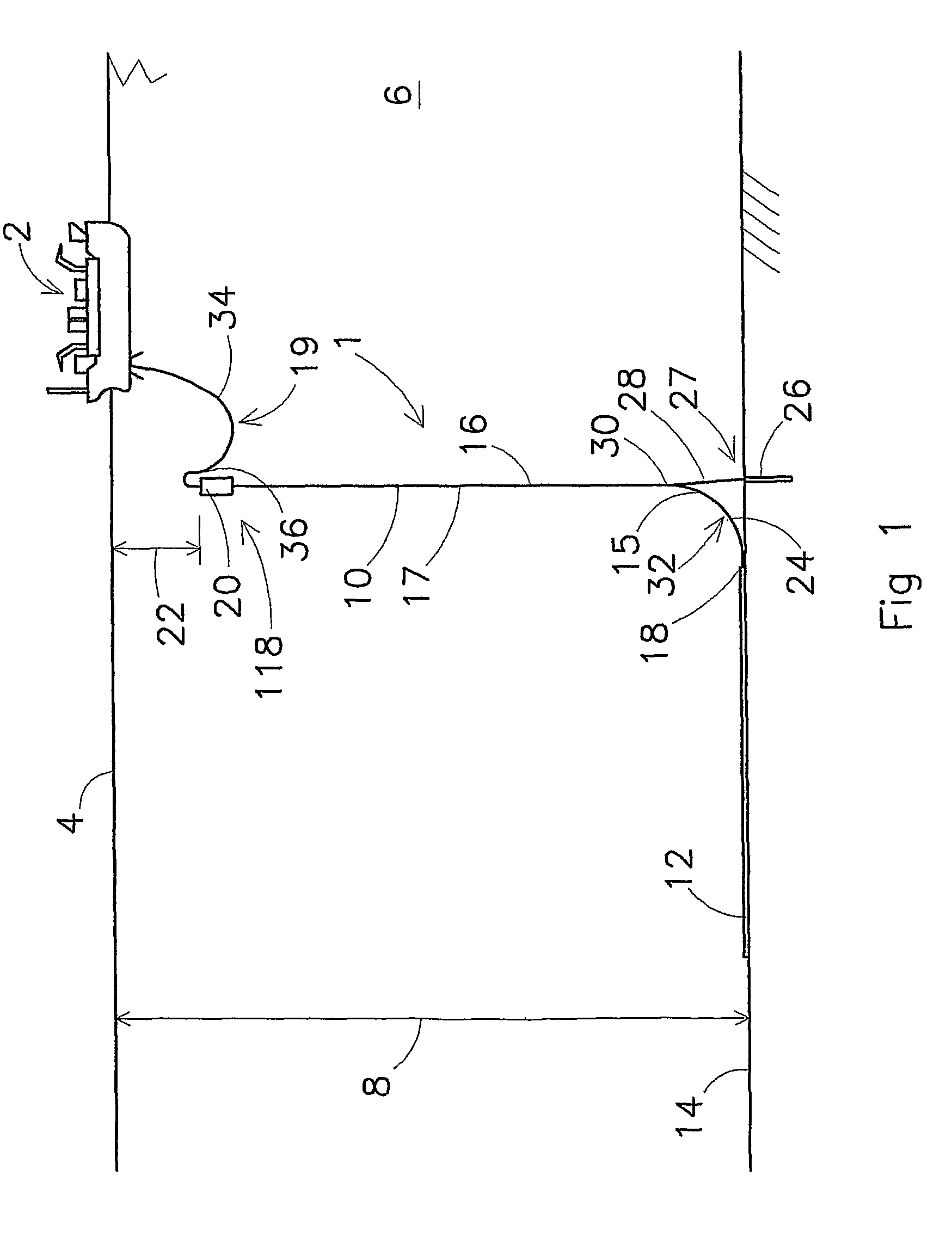
[0138]FIG. 1 shows an embodiment of a pipeline assembly 1 according to the invention. A target device 2 is shown, positioned at a water surface 4. The target device 2 may be an FPSO, or a different kind of vessel. The water 6 may have a substantial depth 8, for instance ranging between one and three kilometres.

[0139]A pipeline 10 comprises a seabed section 12, which rests on a seabed 14, and a riser section 16, which extends from a touchdown point 18 at the seabed 14 to a buoyancy device 20, positioned at a depth 22 under the water surface 4. The buoyancy device 20 exerts an upward force on the pipeline 10. The depth 22 is chosen such, that the buoyancy device 20 is substantially free of forces of waves and wind. At least one flexible pipeline 34 connects a delivery end 36 of the pipeline 10 to the target device 2 for providing a fluid connection between the delivery end 36 and the target device 2. The seabed section 14 may be connected at one end thereof to an oil well (not shown)....


PUM


Abstract

The invention relates to a pipeline assembly and a method of installing a pipeline assembly, wherein the pipeline extends at least in part on a seabed and curves upwardly from the seabed along a curved section thereof, the pipeline extending toward a delivery end provided at the water surface, wherein a connecting device connects the pipeline at a coupling point to an anchoring device at the seabed for preventing the coupling point from moving upward.The invention further relates to a pipeline device comprising at least two pipeline assemblies which are interconnected at a substantial distance from the seabed.

Description

CROSS-REFERENCE TO RELATED APPLICATIONS[0001]This application is the National Stage of International Application No. PCT / NL2006 / 000507, filed Oct. 9, 2006, which is a continuation-in-part of U.S. application Ser. No. 11 / 245,477, filed Oct. 7, 2005, now abandoned the contents of which is incorporated by reference herein.FIELD OF THE INVENTION[0002]The present invention relates to a pipeline assembly. The present invention further relates to a method for installing the pipeline assembly.DESCRIPTION OF THE PRIOR ART[0003]Pipelines are widely applied in the off-shore industry, for instance for conveying a fluid or a mixture of fluids from an oil well on a seabed to a target device located at a water surface. This target device may be a vessel or a platform, for instance a floating production and storage platform, generally known as an FPSO.[0004]Often, a pipeline is laid which rests on a seabed over a certain distance and rises from the seabed at a certain point, which is generally know...

Claims


Application Information

Patent Timeline
Patent Type & Authority Patents(United States)
IPC IPC(8): F16L1/12
CPCB63B27/24E21B17/012E21B17/015E21B17/017F16L1/18F16L1/19F16L1/20
Inventor WOLBERS, DIRK RIENTSCOPPENS, TON
Owner HEEREMA MARINE CONTRACTORS NEDERLAND SE
Why Eureka
Try Eureka