To rotorcraft rotors fitted with inter-blade dampers

a technology of inter-blade dampers and rotors, which is applied in the direction of propellers, propulsive elements, water-acting propulsive elements, etc., can solve the problems of difficult to balance forces in translation, the oscillation of each blade about its drag axis can become coupled, and the material fatigue phenomenon is harmful to materials, etc., to achieve the effect of increasing the lifetime of the inter-blade damper and its damping performance, and reducing the level of inter-blade oscil

Active Publication Date: 2012-02-28
EUROCOPTER
View PDF5 Cites 8 Cited by
  • Summary
  • Abstract
  • Description
  • Claims
  • Application Information

AI Technical Summary

Benefits of technology

[0044]As a result, the invention makes it possible to reduce considerably the level of inter-blade oscillation at the frequency of rotor rotation, thus making it possible to increase the lifetime of the inter-blade damper and its damping performance.

Problems solved by technology

Consequently, the resultant of the aerodynamic forces exerted on a blade does not have the same value at each azimuth position, nor does it have the same point of application: the fixed-end moment at the blade root is thus high and varying, leading to alternating stresses that give rise to a fatigue phenomenon that is harmful to materials.
In addition, the resultant of the aerodynamic forces on all of the blades is no longer directed along the axis of the rotor, thereby creating a roll moment that increases with increasing speed and that can make it difficult to balance forces when flying in translation.
Nevertheless, the oscillations of each blade about its drag axis can become coupled in unstable manner with the movements or the elastic deformation modes of the fuselage, in particular the oscillations of a helicopter standing on the ground on its landing gear: this is at the origin of the phenomenon known as “ground resonance” that can be dangerous for the aircraft when the natural frequency of the oscillations of the blades about their drag axis is close to one of the natural frequencies of the oscillations of the aircraft on its landing gear.
When rotor blades are excited in drag, the blades move away from their equilibrium position and can be distributed unequally in the circumferential direction, thereby creating an unbalance due to the center of gravity of the rotor being displaced away from its axis of rotation.
There is a risk of instability on the ground when the frequency at which the fuselage on its undercarriage is excited is close to the natural oscillation frequency |Ω+ωδ| or |Ω−ωδ|, which corresponds to the phenomenon known as ground resonance.
In practice, it has been found that the disposition of the two ball joints fastening the drag damper as close as possible to each other and to the pitch-changing axis of the blade leads to structures that are complex and that produce results that are disappointing in terms of decoupling pitch, drag, and flapping oscillations.

Method used


Image

  • To rotorcraft rotors fitted with inter-blade dampers
  • To rotorcraft rotors fitted with inter-blade dampers
  • To rotorcraft rotors fitted with inter-blade dampers

Examples


Embodiment Construction

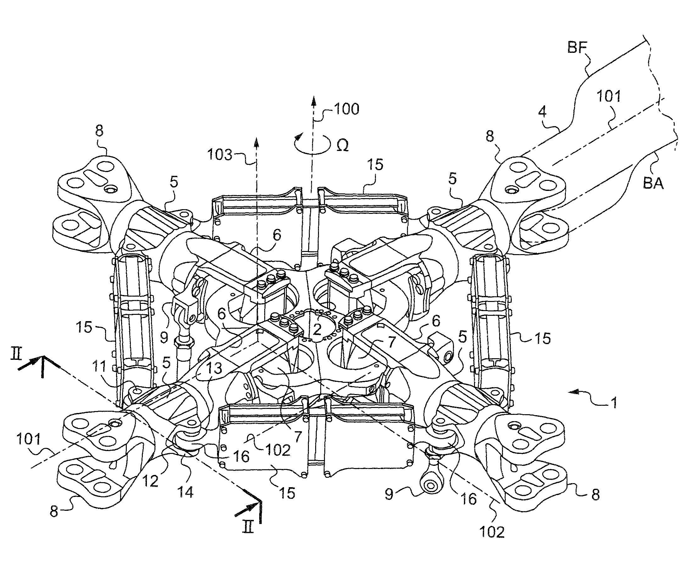
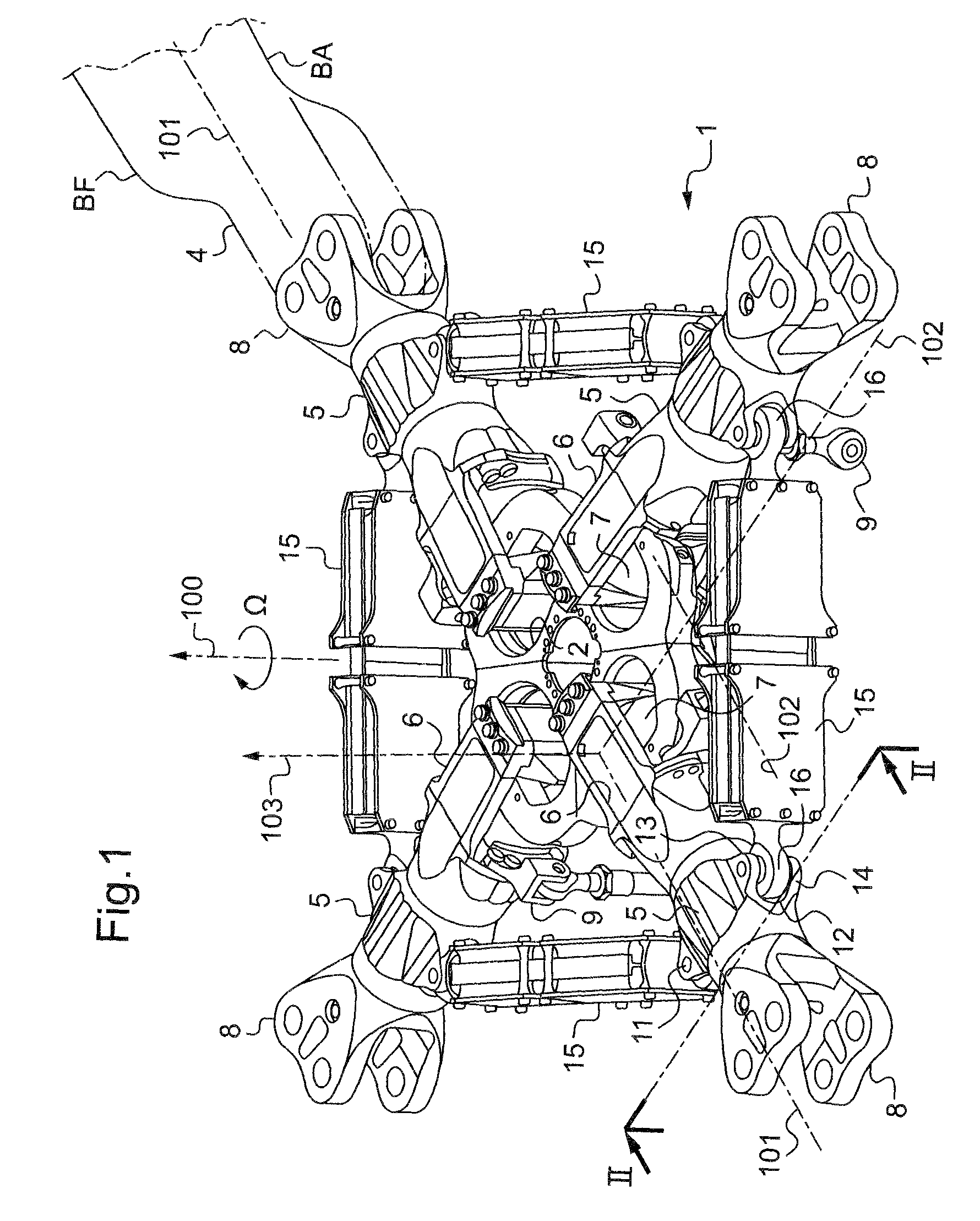
[0059]FIG. 1 shows a portion of a four-blade rotor head 1 of a rotorcraft having a rigid hub 2 constrained to rotate with a rotor mast (not shown) about an axis of rotation 100, with the speed of rotation of the hub 2 being referenced Ω.

[0060]The rotor mast is secured to a main power transmission gearbox (MGB) and transmits lift from the rotor to the structure of the rotorcraft and supports the blades 4 that transform the mechanical energy from the engines into aerodynamic forces.

[0061]Thus, the hub 2 serves as an attachment point for each of the blades 4 via a respective sleeve 5 having an inner radial yoke 6 fitted with a laminated spherical joint 7 (or spherical abutment) connecting it to the hub 2, and with an outer radial yoke 8 or fitting for retaining the corresponding blade 4.

[0062]Under such conditions, each laminated spherical joint 7 allows each corresponding blade 4 to move in vertical flapping about an axis 102 for vertical flapping, in drag, and also in pitch variation...


PUM


Abstract

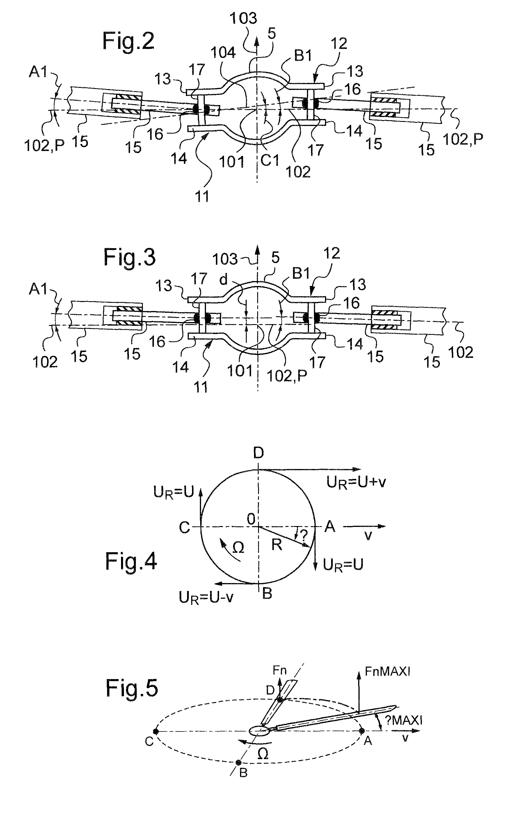
The present invention relates to an improvement to rotorcraft rotors (1) fitted with inter-blade drag dampers (15) such that for each blade (4), the two joints (16) connecting said blade (4) to two inter-blade drag dampers (15) are disposed on either side of the pitch variation axis (101) of said blade, at least one of the two joints (16) being offset to above the plane P containing the pitch variation axis (101) and the vertical flapping axis (102).

Description

[0001]The present invention relates to an improvement to rotorcraft rotors fitted with inter-blade dampers.[0002]The technical field of the invention is that of manufacturing helicopters in particular.BACKGROUND OF THE INVENTION[0003]The invention relates to rotorcraft rotors comprising a hub driven in rotation about an axis of rotation by a drive shaft or outlet shaft from a power transmission gearbox, and also having at least three blades fixed to the hub via appropriate hinges, in particular via respective laminated spherical abutments dedicated to each of the blades, with inter-blade dampers interconnecting each pair of two adjacent blades.[0004]On the assumption that each blade is inserted in a hub in fixed manner, the resulting rotor would be a rigid rotor. When hovering, the distribution of aerodynamic forces along a blade leads to a bending moment distribution presenting a value that is very large at the root of the blade. While flying in translation, the so-called “retreati...

Claims


Application Information

Patent Timeline
Patent Type & Authority Patents(United States)
IPC IPC(8): B64C27/51
CPCB64C27/35B64C27/51Y10S416/50
Inventor BEROUL, FREDERIC
Owner EUROCOPTER
Why Eureka
Try Eureka