Input device and manufacturing method thereof

a manufacturing method and input device technology, applied in the direction of contact mechanisms, pulse techniques, instruments, etc., can solve the problems of poor adjustment of manufacturing process, increased manufacturing cost, and uncomfortable touch sensation, and achieve the effect of low cos

Active Publication Date: 2012-02-28
PANASONIC CORP
View PDF26 Cites 56 Cited by
  • Summary
  • Abstract
  • Description
  • Claims
  • Application Information

AI Technical Summary

Benefits of technology

[0013]The exemplary embodiment of the present invention relates to an input device that comprises a plurality of keys, a position input sensor that is disposed under the keys and that allows detection of input status based on a change of electrostatic capacitance due to displacement of a finger or a conductor on the keys, a base sheet disposed underneath the position input sensor, push-down-input type movable contacts made of a thin metal sheet disposed below the base sheet formed in the shape of an upwardly protruding dome having a circular or elliptical contour and located corresponding to positions of the keys, and a columnar section provided in a manner sandwiched between the position input sensor and the base sheet. As the columnar section is provided in contact with the position input sensor and the base sheet at a position corresponding to the center of the movable contacts, the need for positioning to prevent worsening of touch is eliminated and an inexpensive input device is provided that allows comfortable push-down inputting operation and position inputting operation.
[0015]Also, the position input sensor of the present invention comprises a sensor sheet made by forming a conductive material such as silver and copper into a predetermined electrode pattern, where the electrode pattern is formed in a manner avoiding the portion where the columnar section and the position input sensor are in contact. With this, the electrode pattern can be isolated from the stress due to push-down operation. At the same time, when joining the columnar section to the position input sensor or the base sheet, ultraviolet light can be fully transmitted to stabilize adhesion at the location.
[0017]An exemplary embodiment of the present invention includes a method for manufacturing the input device in which the adhesive layer is pattern-printed on the rear face of the base sheet, followed by forming the contour and holes, attaching movable contacts via the adhesive layer, securing the columnar section on the top face of the base sheet by means of a UV-curable adhesive after positioning it in the center of the movable contact with reference to the contour or hole of the base sheet, and securing the position sensor on the top face of the columnar section by means of a UV-curable adhesive. Thus, an input device that enables push-down inputting operation and position inputting operation using the same operating unit can be manufactured at a low cost.

Problems solved by technology

The difference in the strokes is felt by the finger making the touch uncomfortable feeling.
This causes an increase in the manufacturing cost as the workability of adjustment in the manufacturing process is poor.
However, when columnar section 103 is joined at a position displaced from the center of dome-shaped element 107, the state of inversion of dome-shaped element 107 during push-down operation becomes asymmetrical and original reaction force and stroke cannot be obtained thus worsening the touch feeling.
Accordingly, even when adopting this configuration, workability further worsens thus suffering an increase in the cost.

Method used


Image

  • Input device and manufacturing method thereof
  • Input device and manufacturing method thereof
  • Input device and manufacturing method thereof

Examples


Embodiment Construction

[0027]Referring to FIG. 1 to FIG. 8, a description of an exemplary embodiment of the present invention will be given in the following.

Exemplary Embodiment

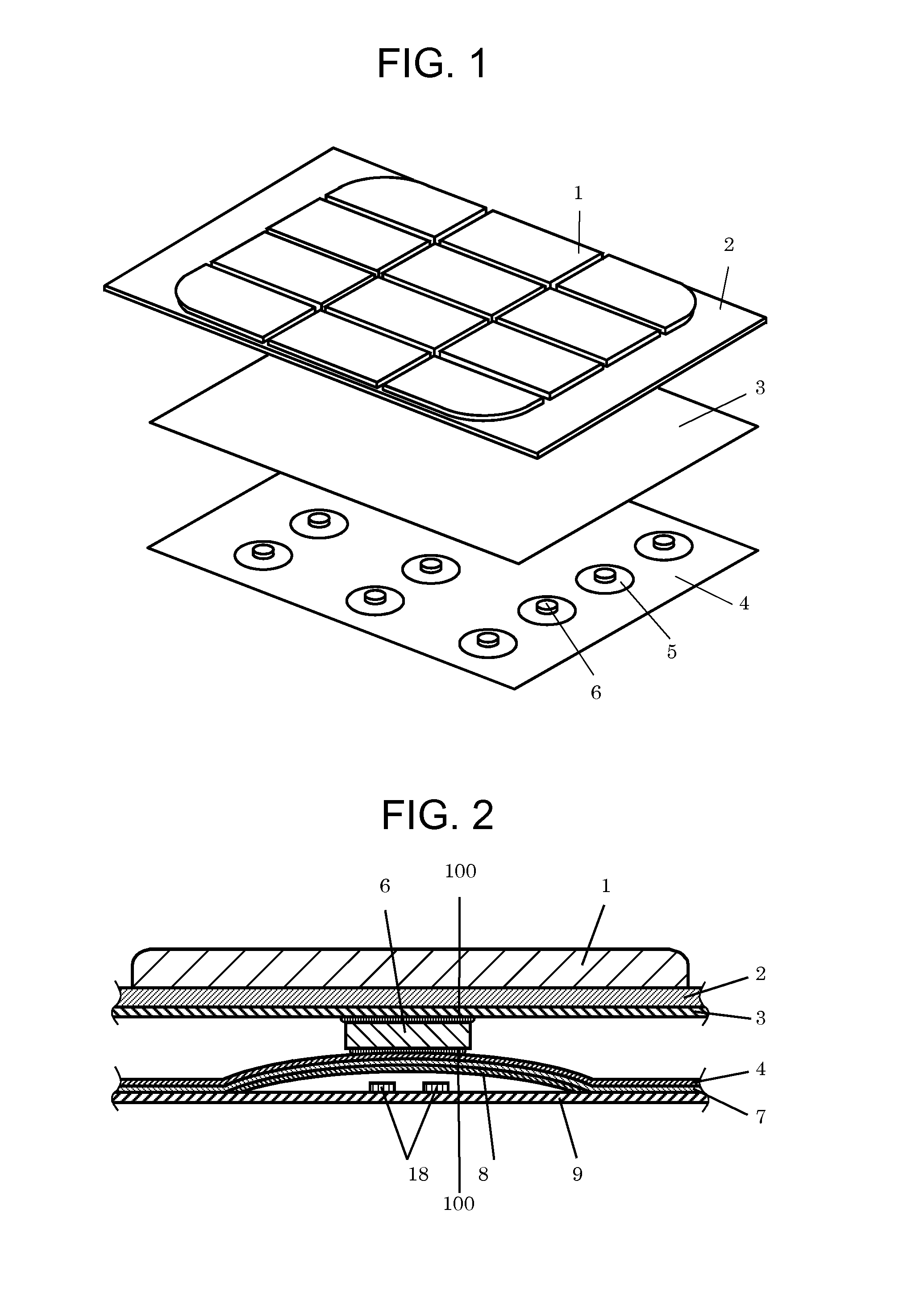
[0028]FIG. 1 is an exploded perspective view of in input device in an exemplary embodiment of the present invention. FIG. 2 is a sectional view of the input device.

[0029]As illustrated in the diagram, plural keys 1 made of a plastic material such as polycarbonate are arranged on the primary surface of the input device. Keymat 2 made of an elastic material such as silicone rubber is disposed under key 1. Key 1 and keymat 2 may be made of the same material or may be formed as an integral unit.

[0030]The bottom face of keymat 2 is formed flat and position input sensor 3 is joined to the bottom face of keymat 2 through an adhesive layer (not shown). Position input sensor 3 is configured by patterning an electrode (not shown) made of silver, for example, on a transparent PET film and the like and is connected to a control unit (not shown...


PUM

PropertyMeasurementUnit
electrostatic capacitanceaaaaaaaaaa
conductiveaaaaaaaaaa
electroluminescentaaaaaaaaaa

Abstract

An input device for constructing an inputting operation unit for various electronic apparatus and a method of manufacturing the input device are provided. The input device allows push-down inputting operation and position inputting operation using the same operating unit. The input device has a position input sensor provided under a key, and a base sheet having a movable contact joined to its bottom face depending on the location where the key is disposed, and a columnar section is disposed in a manner sandwiched between the position input sensor and the base sheet at the center of the movable contact.

Description

FIELD OF THE INVENTION[0001]The present invention relates to input devices that constitute an inputting operation unit for various electronic apparatus and method of manufacturing the input devices.BACKGROUND OF THE INVENTION[0002]As an inputting operation unit for various electronic apparatus, input devices provided with push-button type input means are in wide use such as in portable telephones. By manipulating such an input device, telephone numbers can be inputted into a portable telephone.[0003]Also, as Internet connectivity environment is put in place in recent years, frequent Internet access is practiced giving rise to need to freely move a cursor on a display.[0004]In order to make such an operation, input devices that combine a position input device for moving a cursor on a display and a push-down device for inputting telephone numbers and the like have been contrived.[0005]A description of such a conventional input device will be given below with reference to FIG. 9.[0006]...

Claims


Application Information

Patent Timeline
Patent Type & Authority Patents(United States)
IPC IPC(8): H03K17/795G06F3/033G06F3/0354G06F3/041
CPCG06F3/0202G06F3/03547G06F3/0414H01H13/807H01H2003/0293Y10T29/49105H01H2221/006H01H2221/05H01H2223/0345H01H2225/002H01H2225/03H01H2205/016H04M1/23H01H13/702
Inventor TATEHATA, NAOKINAKAYAMA, HIROSHI
Owner PANASONIC CORP
Why Eureka
Try Eureka