High contrast grating integrated vcsel using ion implantation

a high contrast grating and ion implantation technology, applied in the field of vcsels, can solve the problem of extremely difficult to produce vcsels beyond 1.3 m

Inactive Publication Date: 2011-11-17
RGT UNIV OF CALIFORNIA
View PDF5 Cites 81 Cited by
  • Summary
  • Abstract
  • Description
  • Claims
  • Application Information

AI Technical Summary

Benefits of technology

[0013]The present invention provides a number of novel teachings for use in fabricating long-wavelength VCSELs and their p-side mirrors and current confinement technique. These teachings include use and fabrication of a high contrast grating (HCG) as a top mirror, and mechanisms of forming a current aperture and toward removing most p-doped materials by inserting a tunnel junction near the active region, which allows most p-materials to be replaced by n-materials.

Problems solved by technology

HCG VCSELs have been demonstrated operating at a wavelength of 850 nm on a GaAs-based platform, however, using the GaAs material platform it is extremely difficult to produce VCSELs beyond 1.3 μm.

Method used


Image

  • High contrast grating integrated vcsel using ion implantation
  • High contrast grating integrated vcsel using ion implantation
  • High contrast grating integrated vcsel using ion implantation

Examples


embodiment 1

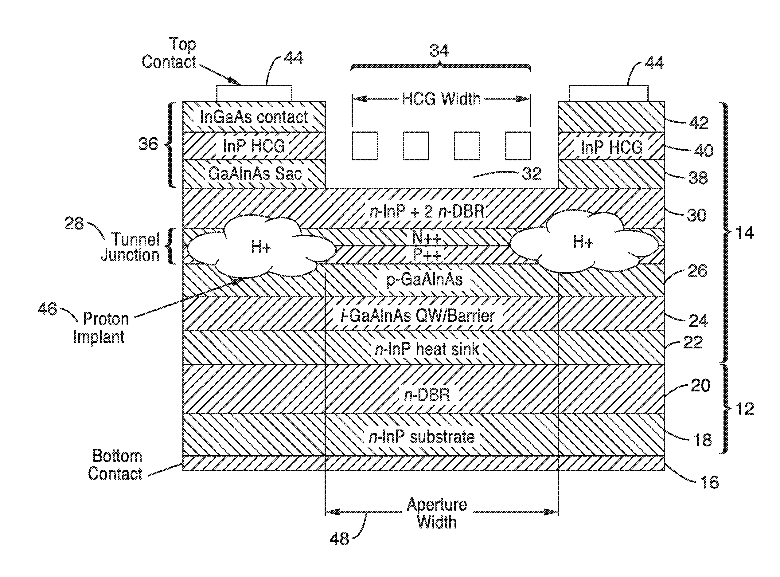
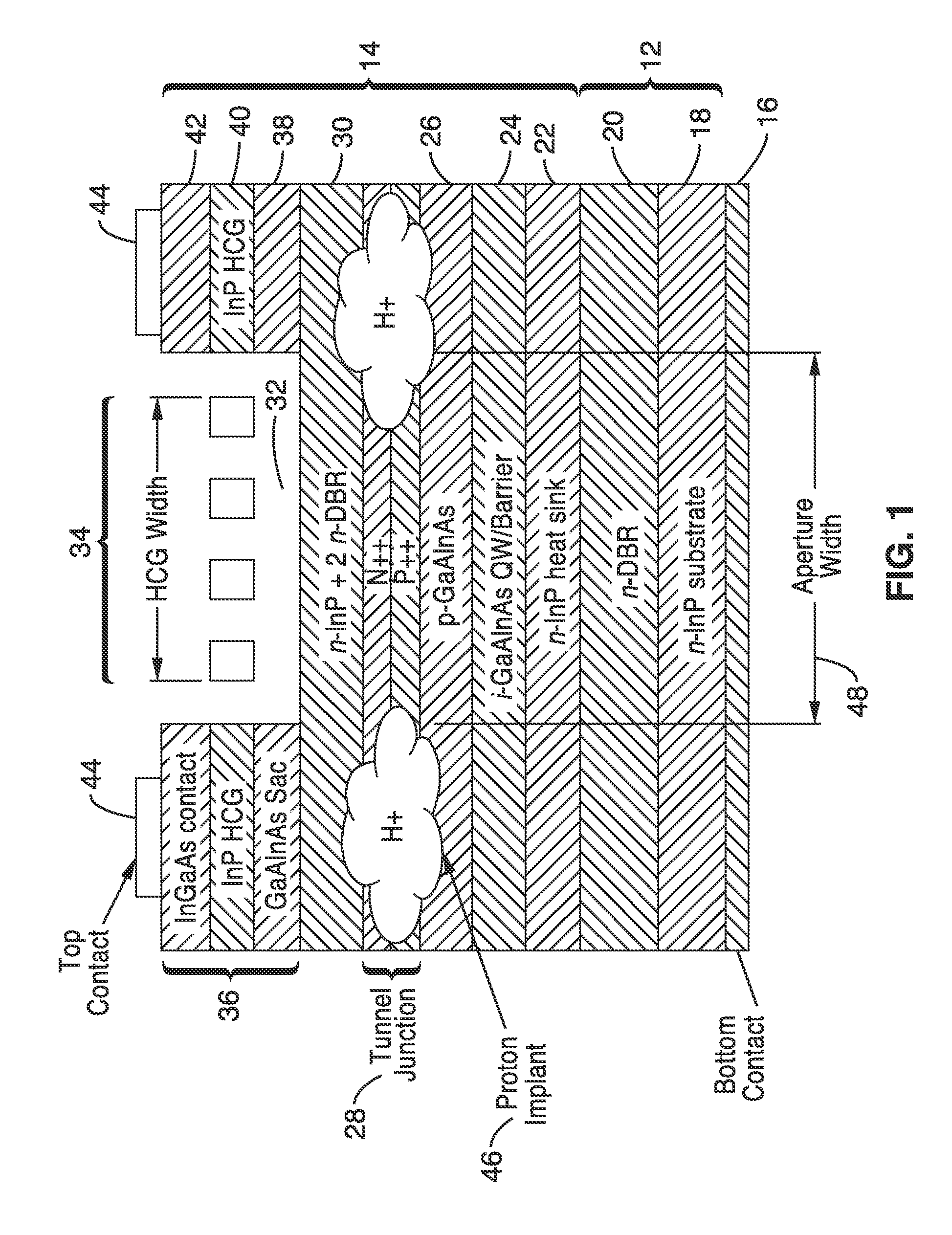
[0095]2. The apparatus of embodiment 1, wherein said electrical confinement layer comprises ion implantation surrounding an aperture having a desired aperture width.

[0096]3. The apparatus of embodiment 1, wherein said ion implantation comprises proton implantation.

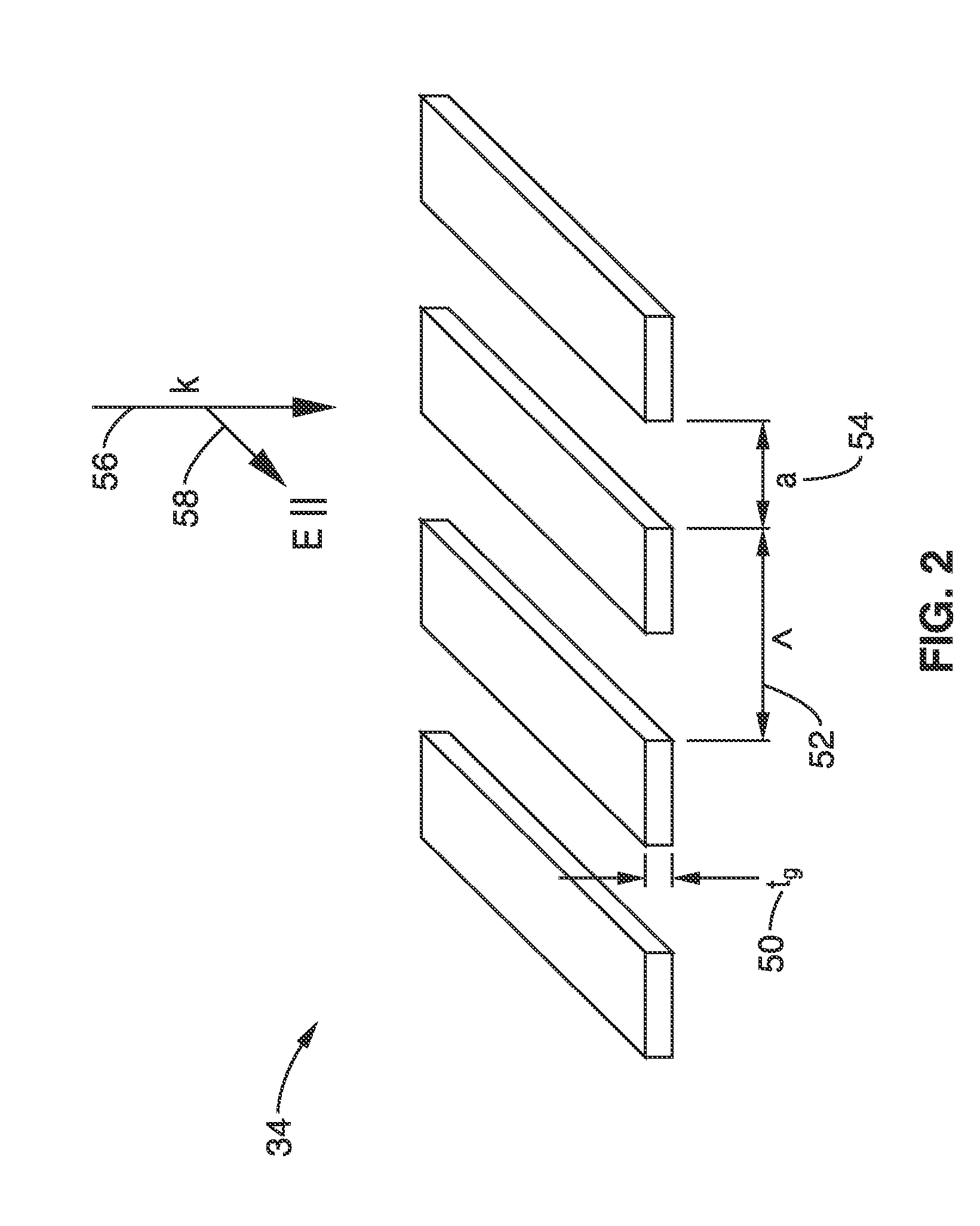
[0097]4. The apparatus of embodiment 1, wherein said high-contrast grating (HCG) provides optical confinement by acting as a lens.

[0098]5. The apparatus of embodiment 1: wherein said high-contrast grating (HCG) provides optical confinement by acting as a lens; wherein said HCG is configured for optical phase variation in response to non-uniform grating spacing to provide optical focusing of the light interacting with said HCG.

[0099]6. The apparatus of embodiment 1, wherein material for said high-contrast grating (HCG) is selected from a group of semiconductor materials consisting of Indium Phosphide (InP), InGaAlAs, or GaAlAs.

[0100]7. The apparatus of embodiment 1, further comprising an electrical conduction layer disposed...

embodiment 8

[0102]9. The apparatus of embodiment 8, wherein said micro-mechanical actuator comprises an electrostatic force actuator which is actuated in response to an applied voltage level.

[0103]10. The apparatus of embodiment 8, wherein said micro-mechanical actuator comprises a thermal actuator which is actuated in response to an applied current.

[0104]11. The apparatus of embodiment 1, wherein said apparatus comprises a vertical cavity surface emitting laser (VCSEL) configured for output emissions in the 0.85 μm to 2.3 μm wavelength range.

[0105]12. The apparatus of embodiment 1, wherein said apparatus comprises a vertical cavity surface emitting laser (VCSEL) fabricated from Indium Phosphide (InP).

[0106]13. The apparatus of embodiment 1, further comprising: a sacrificial layer disposed between said high-contrast grating (HCG) and said electrical confinement layer; wherein the depth and wavelength of said vertical resonator is determined in response to the extent of removal of said sacrifici...

embodiment 14

[0108]15. The apparatus of embodiment 14, further comprising a tunnel junction disposed over said active layer for removing the majority of p-doped materials.

[0109]16. The apparatus of embodiment 14, wherein said apparatus comprises a vertical cavity surface emitting laser (VCSEL) fabricated from Indium Phosphide (InP) lattice matched materials.

[0110]17. The apparatus of embodiment 14, further comprising: a micro-mechanical actuator coupled to said high-contrast grating (HCG); wherein said HCG is movably retained over said vertical resonator cavity; and wherein the depth of the vertical resonator cavity is changed, to alter the wavelength of the second portion of the light which is output, in response to one or more actuation levels of said micro-mechanical actuator.


PUM


Abstract

A Vertical Cavity Surface Emitting Laser (VCSEL) and its fabrication are taught which incorporate a high contrast grating (HCG) to replace the top mirror of the device and which can operate at long-wavelengths, such as beyond 0.85 μm. The HCG beneficially provides a high degree of polarization differentiation and provides optical containment in response to lensing by the HCG. The device incorporates a quantum well active layer, a tunnel junction, and control of aperture width using ion implantation. A tunable VCSEL is taught which controls output wavelength in response to controlling a micro-mechanical actuator coupled to a HCG top mirror which can be moved to, or from, the body of the VCSEL. A fabrication process for the VCSEL includes patterning the HCG using a wet etching process, and highly anisotropic wet etching while precisely controlling temperature and PH.

Description

CROSS-REFERENCE TO RELATED APPLICATIONS[0001]Not ApplicableSTATEMENT REGARDING FEDERALLY SPONSORED RESEARCH OR DEVELOPMENT[0002]Not ApplicableINCORPORATION-BY-REFERENCE OF MATERIAL SUBMITTED ON A COMPACT DISC[0003]Not ApplicableNOTICE OF MATERIAL SUBJECT TO COPYRIGHT PROTECTION[0004]A portion of the material in this patent document is subject to copyright protection under the copyright laws of the United States and of other countries. The owner of the copyright rights has no objection to the facsimile reproduction by anyone of the patent document or the patent disclosure, as it appears in the United States Patent and Trademark Office publicly available file or records, but otherwise reserves all copyright rights whatsoever. The copyright owner does not hereby waive any of its rights to have this patent document maintained in secrecy, including without limitation its rights pursuant to 37 C.F.R. §1.14.BACKGROUND OF THE INVENTION[0005]1. Field of the Invention[0006]This invention pert...

Claims


Application Information

Patent Timeline
Patent Type & Authority Applications(United States)
IPC IPC(8): H01S5/026
CPCB82Y20/00H01S5/0425H01S5/0612H01S5/105H01S5/18322H01S5/18341H01S5/34306H01S5/18361H01S5/18366H01S5/18386H01S5/18394H01S5/3095H01S5/18355H01S5/11
Inventor CHANG-HASNAIN, CONNIECHASE, CHRISTOPHERRAO, YI
Owner RGT UNIV OF CALIFORNIA
Why Eureka
Try Eureka