
Quick release screw connector for earth-moving equipment

a technology of earth-moving equipment and screw connector, which is applied in the direction of threaded fasteners, bolts, drags, etc., can solve the problems of labor-intensive replacement of welded-on wear plates from the lip, high wear of the teeth mounted to the lip, and high labor intensity of the replacement of welded-on wear plates

Active Publication Date: 2012-03-06
BERKELEY FORGE & TOOL
View PDF26 Cites 26 Cited by
  • Summary
  • Abstract
  • Description
  • Claims
  • Application Information

AI Technical Summary

Benefits of technology

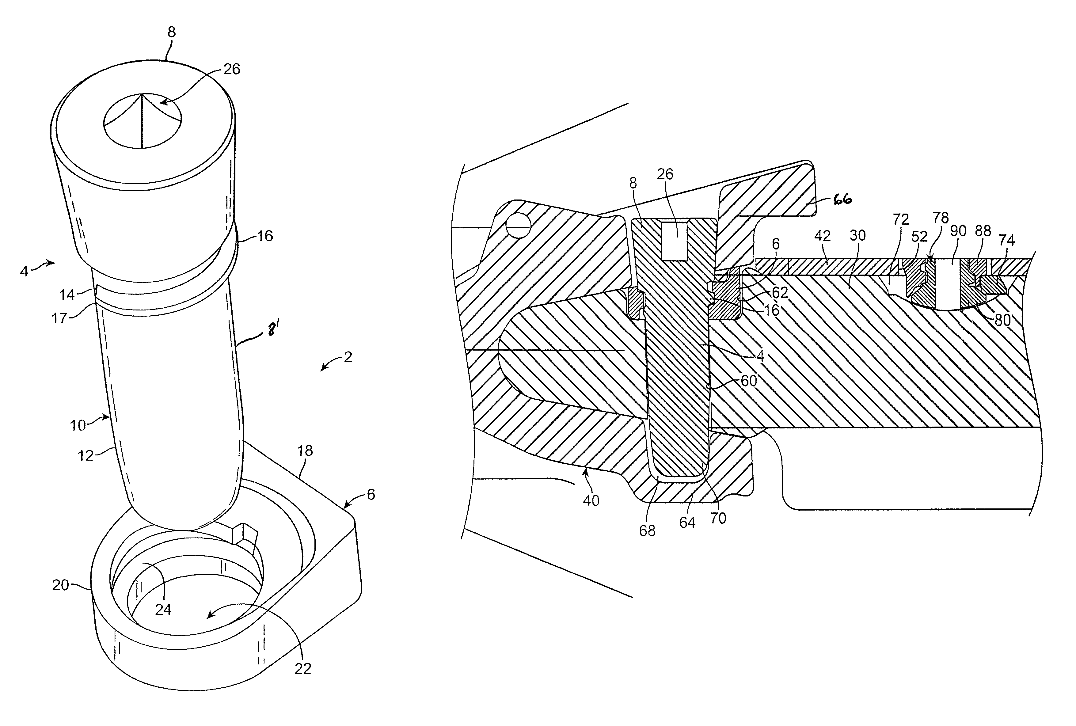
"The present invention provides a unique screw connection for power-driven earth-moving equipment connectors that overcomes the disadvantages of prior art connectors. The screw has a tapered shank and a head for rotating the shank about its axis and engaging a component of the equipment. The screw has a thread that extends over less than one full rotation or circumference of the screw. The nut cooperating with the screw has a complementary, tapered thread that is configured to receive the tapered thread on the screw. The screw and nut are preferably provided with visual indicators that signal to the operator whether the required turn of the screw has been completed. The operator engages the screw head, rotates it in the opening direction, and withdraws the screw from the threaded nut hole to enable replacement of the part or parts in question. The technical effects of this invention include improved durability, reliability, and ease of replacement of components."

Problems solved by technology

The teeth mounted to the lip are subject to much wear and require frequent replacement.
Replacing welded-on wear plates from the lip is labor-intensive.

Method used


Image

  • Quick release screw connector for earth-moving equipment
  • Quick release screw connector for earth-moving equipment
  • Quick release screw connector for earth-moving equipment

Examples


Embodiment Construction

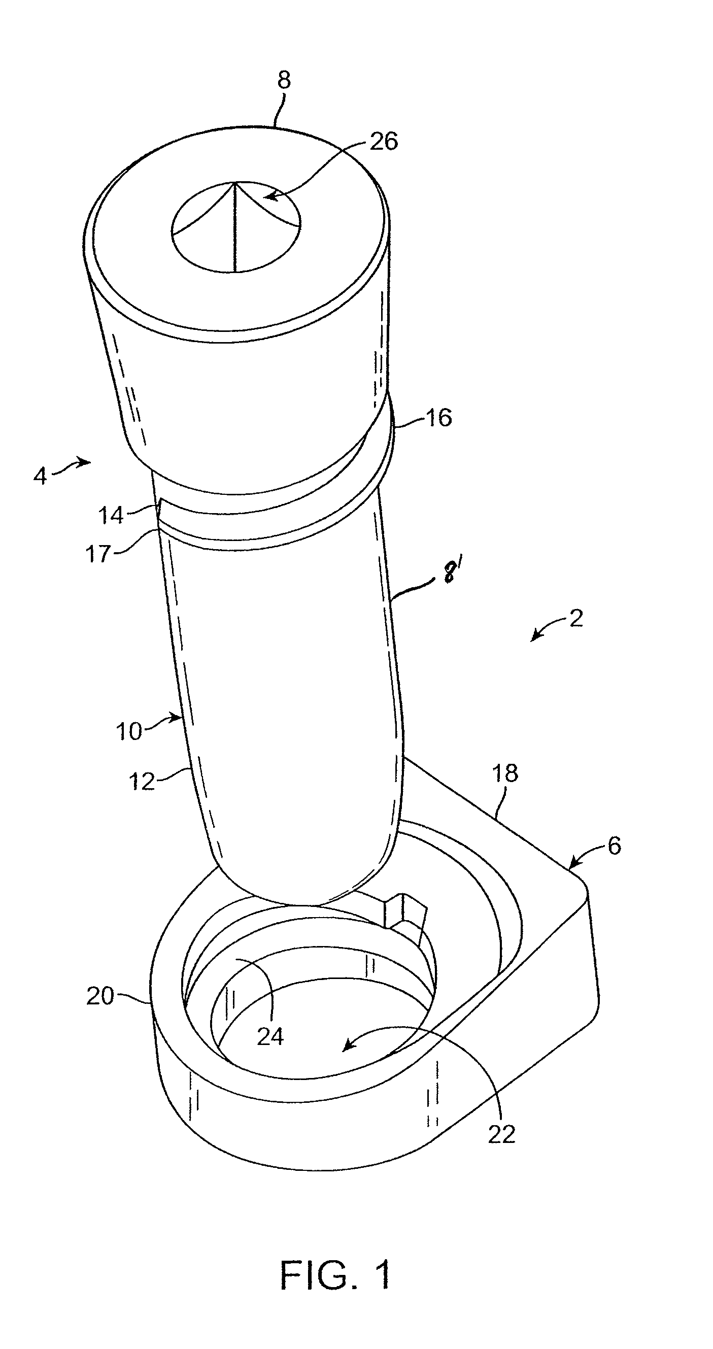
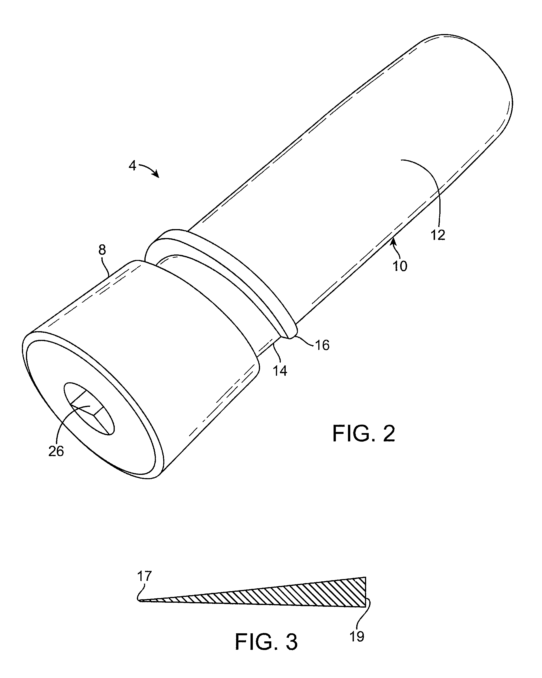
[0022]Referring to FIGS. 1-3, a screw connection 2 constructed in accordance with the present invention has a screw or threaded bolt 4 and a cooperating nut 6. Screw 4 has a screw head 8 at its “upper end” and a shaft 10 that extends coaxially away from the head in a “downward” direction, as illustrated in FIG. 1. The shaft is preferably slightly tapered in a downward direction (away from the screw head) and includes a smooth lower portion 12 and an upper portion 14 over which a three-quarter turn (270°) thread 16 extends from the vicinity of the screw head 8, e.g. beginning at about and preferably slightly below the lower end of the screw head 8 and extending downwardly at the selected helix angle.

[0023]The cross-section of thread 16 and in particular its height is largest at its uppermost end 19 (in the vicinity of the screw head). It gradually and linearly decreases in a downward direction to a thread end point 17 that is typically slightly rounded. FIG. 3 schematically illustrat...


PUM


Abstract

A connector for earth-moving equipment subjected to contact with earth, abrasive materials and the like has a nut with a body and a hole extending through the body. A bolt with a shank adapted to extend into the hole has an enlarged head at one end of the shank. Cooperating thread formations are defined on the shank and in the hole. The thread formations have cooperating matching cross-sections that decrease from a vicinity of the head of the screw towards the other end of the screw and that extend over a circumference of less than 360° and typically of no more than 270°. The connector is adapted to connect various components, including teeth and adapters, to each other and to lips at the front end of earth moving buckets and the like.

Description

CROSS-REFERENCES TO RELATED APPLICATIONS[0001]This application claims priority from pending provisional patent application No. 61 / 139,503 filed Dec. 19, 2008, the disclosure of which is incorporated by reference.BACKGROUND OF THE INVENTION[0002]The present invention is directed to a screw connector for earth-moving equipment and the like adapted to secure components of the equipment to each other with a screw-nut connection that remains operable in environments involving earth, dirt, abrasives and the like.[0003]Earth-moving equipment, such as power-driven shovels, loaders, scoops, dippers and the like, typically has a bucket, the earth-digging front end of which is normally defined by a generally U-shaped heavy-duty lip that is suitably fastened to the bucket. The lip includes a plurality of digging teeth which project from a front edge of the lip as well as wear plates which line interior surfaces of the lip to protect it from being worn down by earth, coal and the like into which...

Claims


Application Information

Patent Timeline
Patent Type & Authority Patents(United States)
IPC IPC(8): E02F9/28
CPCE02F9/2833F16B33/02
Inventor BIERWITH, ROBERT S.
Owner BERKELEY FORGE & TOOL
Learn More