
Paper pallet for packaging

Inactive Publication Date: 2012-03-06
LUSNGWEN +1
View PDF10 Cites 13 Cited by
  • Summary
  • Abstract
  • Description
  • Claims
  • Application Information

AI Technical Summary

Benefits of technology

[0010]An object of the present invention is to provide a paper pallet for packaging, which uses a paper pallet as the load bearing base for the packing of goods, thus replacing the Styrofoam board, wood and metal frame in order to have an environmentally friendly effect and reduce the cost of using.
[0011]Another object of the present invention is to provide a paper pallet for packaging, which allows for protective packaging material to gain better protective capability for transportation.
[0014]The protective packaging material is placed between the packaging protective frame and the cargo to fill the gap between them and strengthen the protection for the cargo. The paper pallet for packaging formed by combining the packaging protective frame with the load bearing base becomes the packing box for packing large cargo when delivering. The paper pallet for packaging also has the advantages of a low manufacturing cost, light weight, no pests, etc., and can be fully recycled and is environmentally friendly.

Problems solved by technology

However, Styrofoam structure is difficult to decompose in nature, and easily produces harmful gases when burning it, which causes immense damage to the environment.
If Styrofoam is not restricted or banned, a worldwide environmental crisis will be caused.
Currently most bearing structures are made of wood or metal frames, which are solid and able to load heavy objects onto, but their weight is too heavy and thus they weigh too much which affects the transportation and the cost thereof.
Moreover, the wood or metal frames are difficult to recycle, production costs therefore remain high, and their disposal is still a major environmental issue.
However, the paper pallet structure in prior art can only be used for stacking and moving goods, and has no special packing box structure designed for delivering goods and does not meet the requirements of being multi-functional.

Method used


Image

  • Paper pallet for packaging
  • Paper pallet for packaging
  • Paper pallet for packaging

Examples


Embodiment Construction

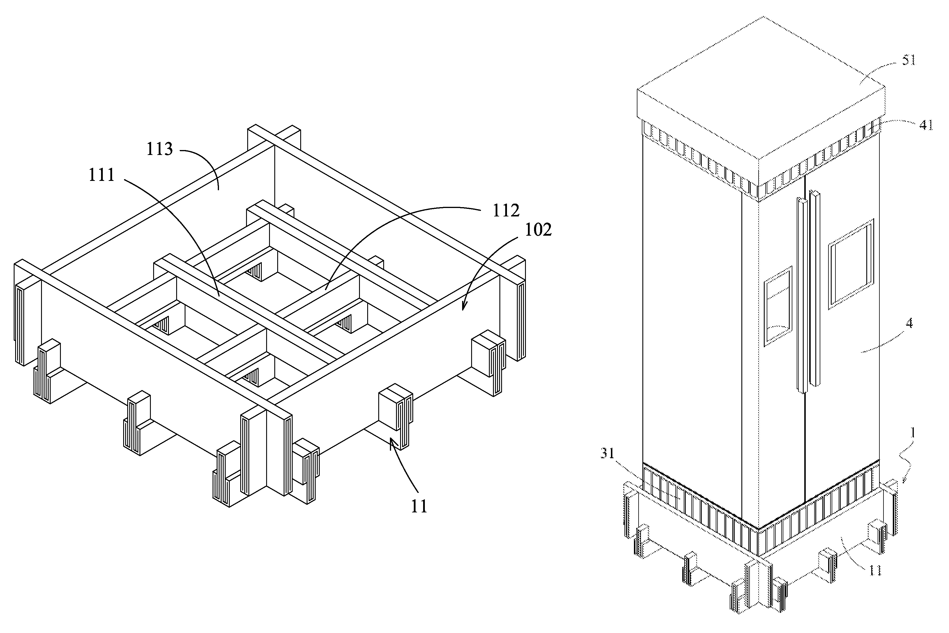
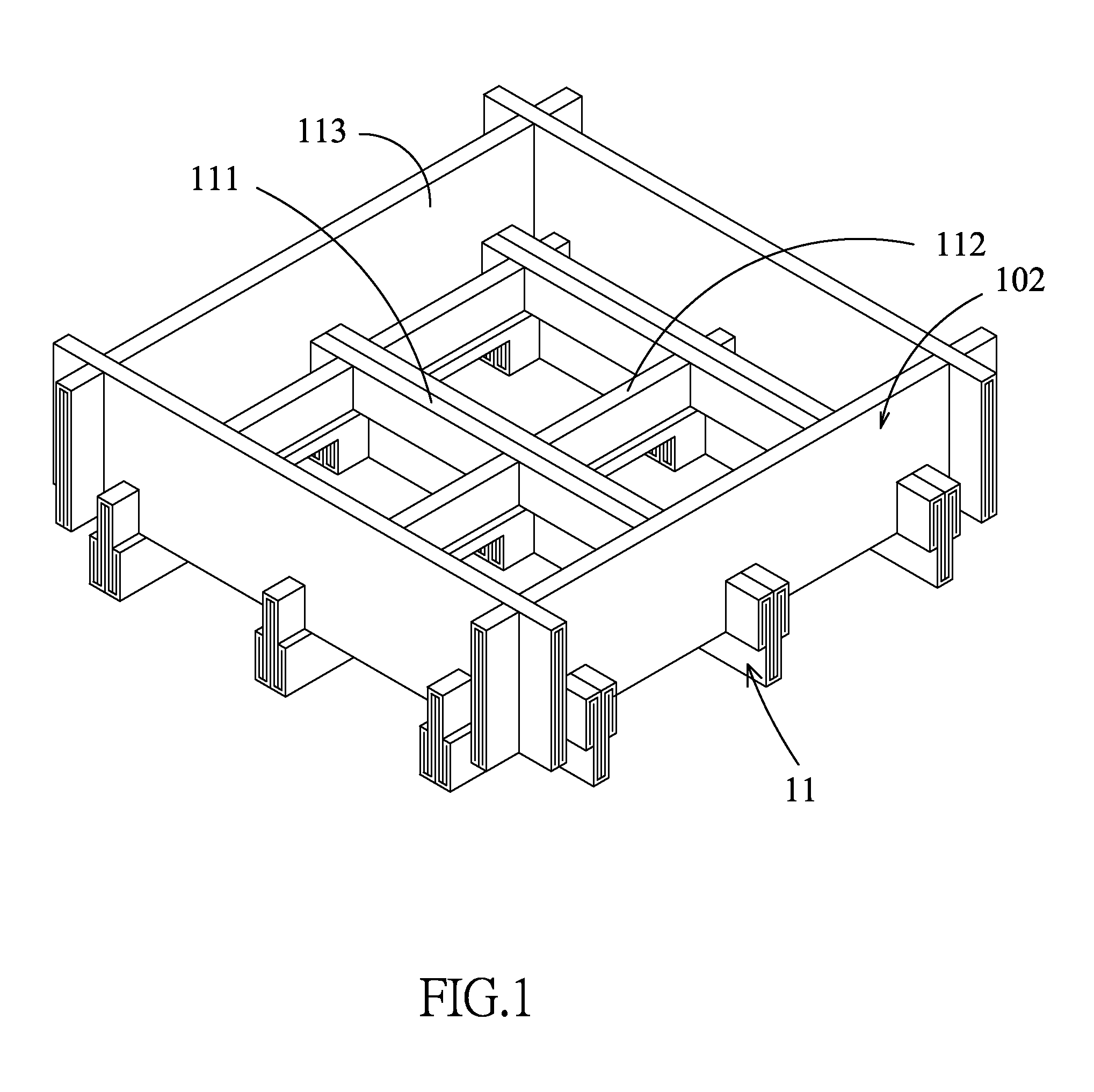
[0024]Please refer to FIGS. 1 and 5, showing a paper pallet for packaging provided by the present invention, which combines the traditional paper pallet with a packaging protective frame 102 and becomes a load bearing base for packaging the goods, so as to carry the goods being sold.

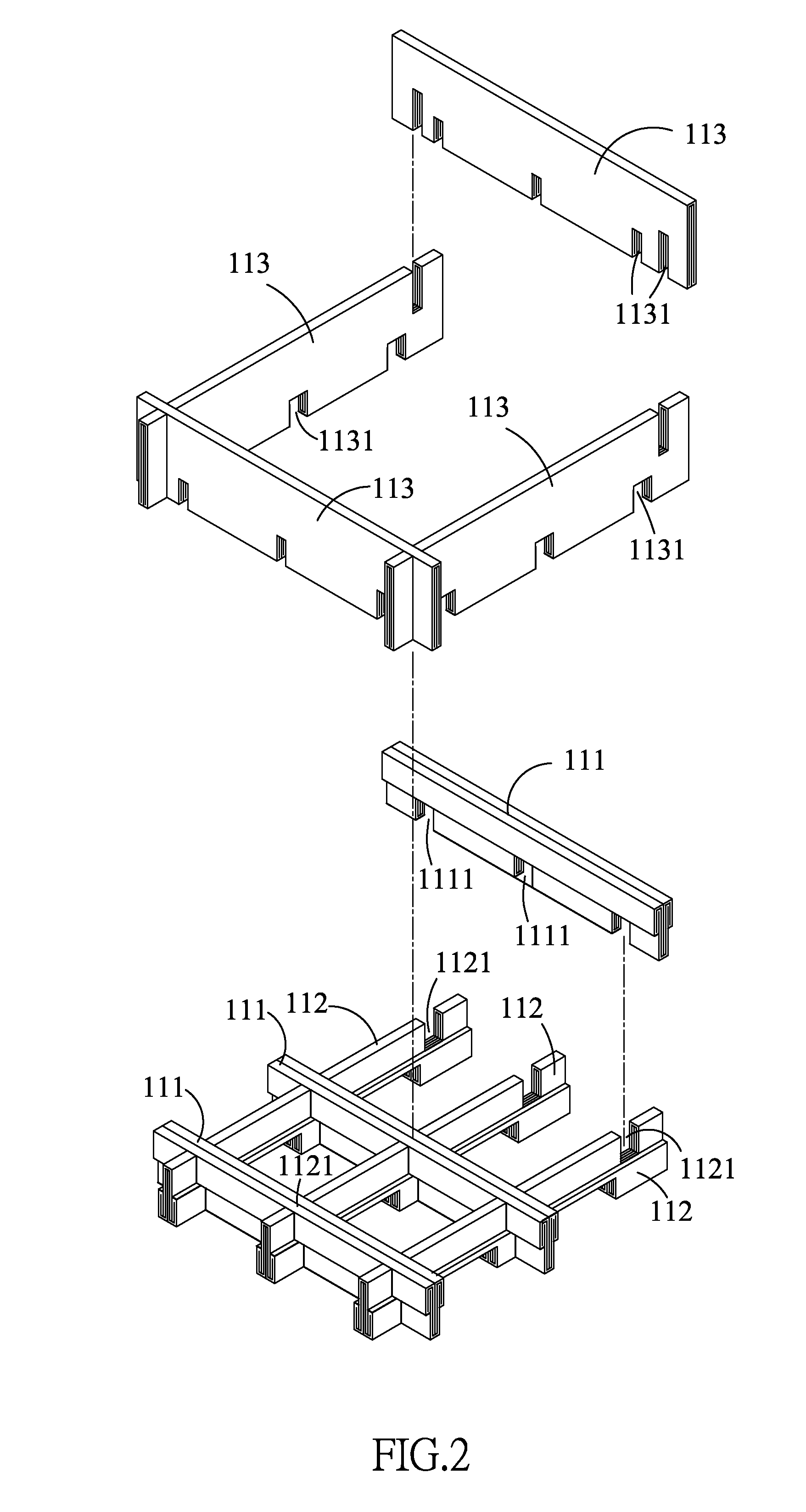
[0025]The paper pallet for packaging includes: a load bearing base 11, a packaging protective frame 102 and a plurality of protective packaging material 31. Please refer to FIGS. 1 and 2, wherein the load bearing base 11 has a plurality of vertical supporting components 111 and a plurality of horizontal supporting components 112, which are formed by a single folded corrugated cardboard, wherein the vertical supporting components 111 and the horizontal supporting components 112 are arranged in a net grid layout to form at least one intersection point. At the intersection point(s), a plurality of first grooves 1111 are set on the vertical supporting components 111 which are relative to the plurality of sec...


PUM


Abstract

A paper pallet for packaging comprising: a load bearing base and a packaging protective frame, wherein the load bearing base is composed of a plurality of vertical supporting components and a plurality of horizontal supporting components. The load bearing base is composed of the vertical supporting components and the horizontal supporting components intersecting and subsequently interlocking with each other, and the packaging protective frame is composed of a plurality of side boards. Therefore, the side boards intersect and subsequently interlock with each other to form a packaging protective frame, which is inlaid at a set distance from the edge around the load bearing base to form a paper pallet for packaging. Thus, the paper pallet for packaging is formed by combining the packaging protective frame with the load bearing base to become the packaging box for delivering goods.

Description

BACKGROUND OF THE INVENTION[0001]1. Field of the Invention[0002]The present invention relates to a paper pallet for packaging, more particularly to a load bearing base constructed by a plurality of supporting components formed by a single folded corrugated board, and a packaging protective frame being inlaid on the edge around the load bearing base, which forms a packaging box for delivering goods.[0003]2. Description of the Related Art[0004]When goods are sold, a packing box will be installed thereon, which can protect the surface of the goods from collision and damage. A traditional packing box structure for goods delivery uses Styrofoam as the bottom plate. Since Styrofoam is light, strong and cheap, it has been widely used for the packing box.[0005]However, Styrofoam structure is difficult to decompose in nature, and easily produces harmful gases when burning it, which causes immense damage to the environment. If Styrofoam is not restricted or banned, a worldwide environmental c...

Claims


Application Information

Patent Timeline
IPC IPC(8): B65D19/00
CPCB65D19/0095B65D19/20B65D81/052B65D2519/00019B65D2519/00054B65D2519/00159B65D2519/00273B65D2519/00293B65D2519/00298B65D2519/00323B65D2519/00333B65D2519/00338B65D2519/00353B65D2519/00497B65D2519/00567B65D2519/00587B65D2519/00641B65D2519/0081B65D2519/00985B65D2585/6817
Inventor LU, SHANG WENKIM, YOUNG-SEOG
Owner LUSNGWEN
Learn More