Flow control device

a flow control and flow control technology, applied in the field of valves, can solve the problems of inconvenient user restriction, insufficient gravity bias, and requiring additional labor, and achieve the effects of reducing space, saving labor, and reducing cos

Active Publication Date: 2012-03-06
NAT DIVERSIFIED SALES
View PDF58 Cites 25 Cited by
  • Summary
  • Abstract
  • Description
  • Claims
  • Application Information

AI Technical Summary

Benefits of technology

[0008]According to a preferred embodiment of the invention, there is described a flow regulation device, or valve, configured to address various disadvantages in the prior art. The valve includes a housing defining an internal chamber with an inlet port and an outlet port. A flapper is positioned within the chamber, and is configured to pivot to a first closed position to seal the inlet port against flow between the outlet port and the inlet port, and to pivot to a second open position to permit fluid flow between the inlet port and the outlet port. A limiting element is located within the chamber, and is adjustably positionable in relation to the flapper to limit the amount by which the flapper pivots. The limiting element may be positioned to prevent the flapper from pivoting at all. The configuration of a check valve in combination with a shut off valve in the same flow regulation device provides the advantage of cost reduction, space reduction, and labor saving when it comes to installation.
[0009]In another aspect of the invention, the limiting element is attached to a rotatable spindle and a first end of the spindle extends outside the housing chamber, the first end including a handle for rotating the spindle, wherein rotation of the handle changes the proximity of the limiting element to the flapper. The spindle has a second end opposite the first end, and preferably the second end terminates inside the housing chamber and is held against translational movement by a cylindrical bearing that is molded as an integral part of the housing. By terminating the second end inside the chamber, the opportunity for a leak to develop is reduced.
[0013]In yet a further aspect of the invention, the flapper includes a rigid door having a first planar surface and, attached to a second surface opposite the first surface, a clasping portion defining an indentation configured to receive a pin. A resilient gasket is attached to the first planar surface. A linking element for linking the door to the rod is provided, the linking element including a cylindrical portion at a first end, the cylindrical portion having a bore for receiving the rod to permit the linking element to rotate about the rod, the linking element further including a pin at a second end, the pin having a first elongate axis and being configured to be held by the indentation. A locking piece is provided and is configured to lock the pin into the indentation by mating detents positioned on the locking piece and on the door. The indentation is shaped in relation to the pin to permit both translational movement of the pin along the axis of the pin, and rotational movement of the pin about the axis of the pin. Preferably, the indentation is further shaped to permit rotational movement about a second axis extending through the pin, perpendicular to the axis of the pin and perpendicular to the first planar surface of the door, but further wherein the indention has a constricted waist to restrict translational movement of the entire pin in all directions other than along the axis of the pin. Under this configuration, the flapper may adjust its position against the inlet port to optimize the quality of the seal.

Problems solved by technology

Both are prone to problems in that gravity may not provide a sufficiently strong bias toward the closed configuration, and where a metal spring is introduced problems of deterioration due to corrosion are typically not far behind.
For example, such prior check do not conveniently allow a user to restrict the amount of forward flow that such a valve will permit.
This solution has the disadvantage of requiring additional labor, additional space for the serial plumbing installation, and additional cost for a separate shut-off valve.

Method used


Image

  • Flow control device
  • Flow control device
  • Flow control device

Examples


Embodiment Construction

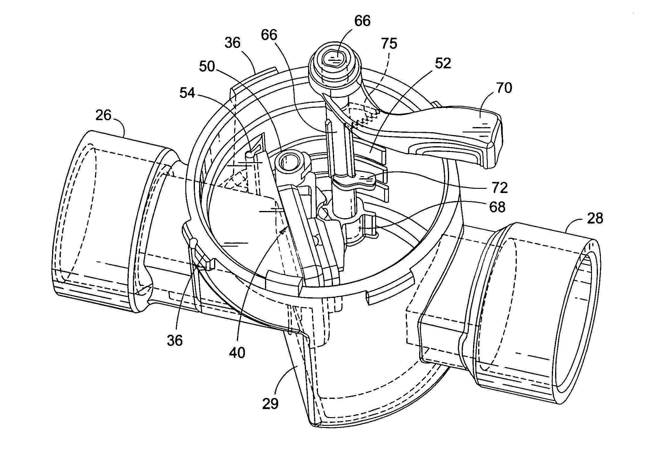
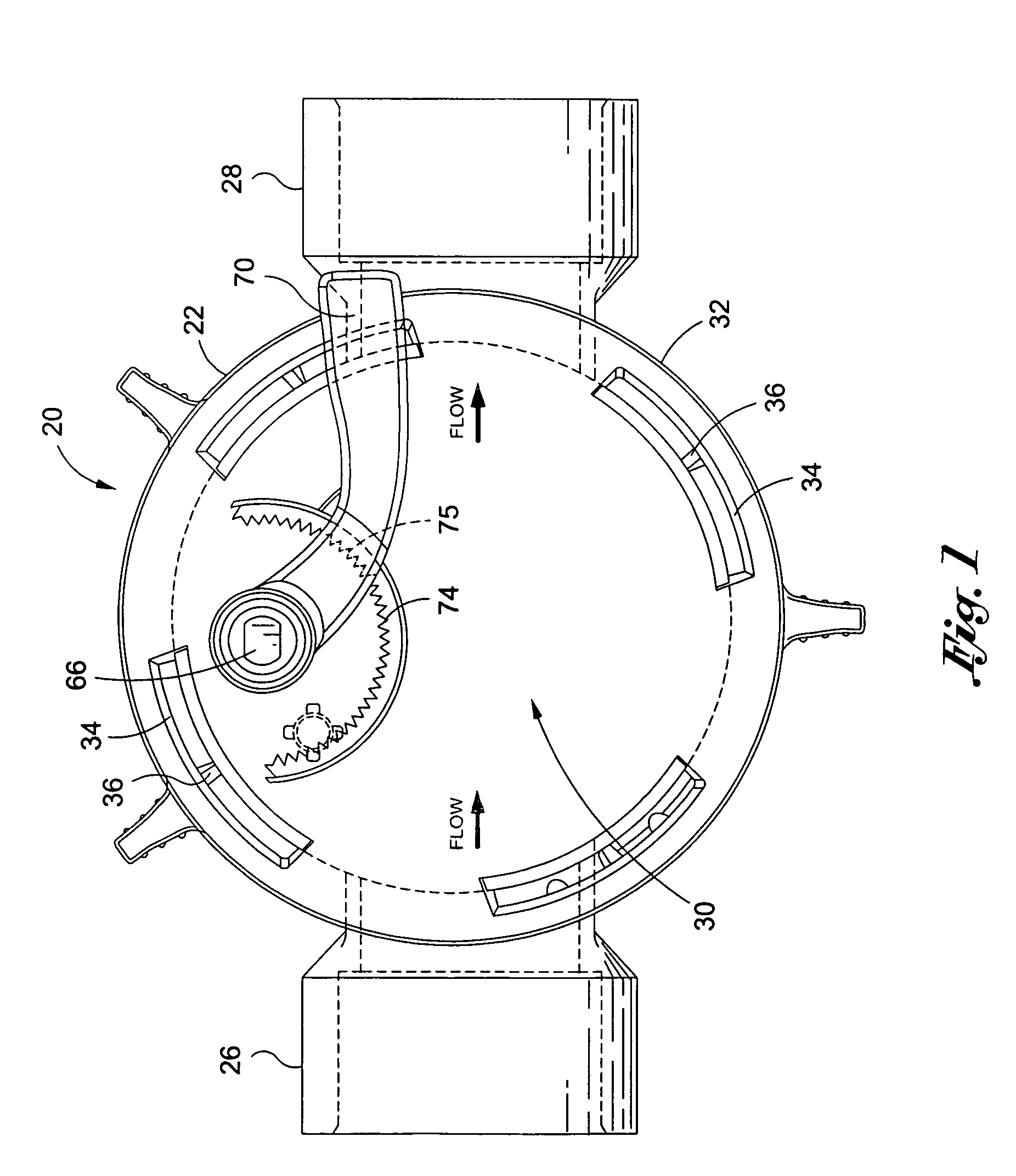
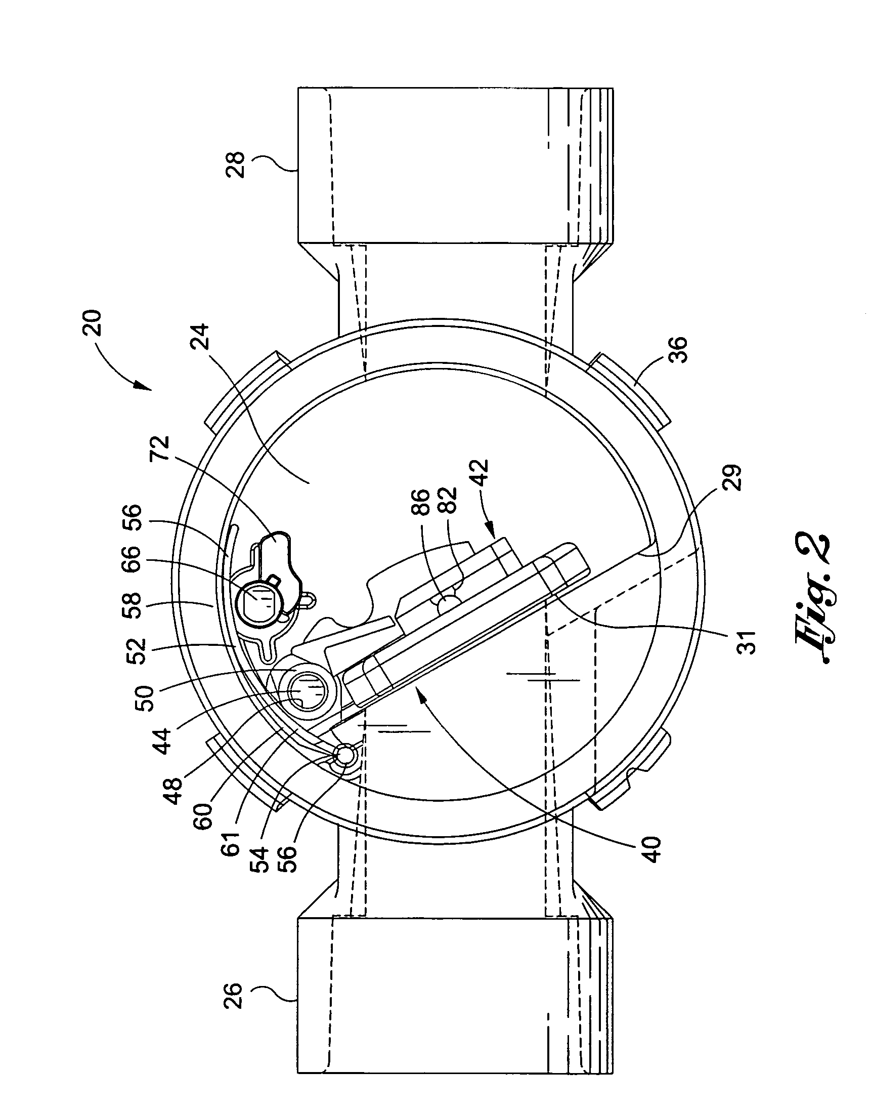
[0022]With reference to the drawings, which are shown only for exemplification and not limitation, there is shown a valve generally identified by the numeral 20, having features of the claimed invention with initial reference to FIGS. 1-4. The valve 20 includes a housing 22, preferably of generally cylindrical shape, having an inner chamber 24 (FIG. 2) that is openable at the top to provide working access. The housing is preferably made of molded PVC, although any suitable material such as iron or brass may be used. The housing defines at least two ports 26, 28 each adapted to be connected with portions of a pipe (not shown) carrying fluid flow through the chamber 24 from inlet port 26 to outlet port 28. The inlet port 26 may enter the chamber via an orifice in a planar wall 29 which is configured to provide a suitable planar seat 31 (FIG. 2) for sealing engagement with a flow regulation mechanism, described below.

[0023]As best seen in FIGS. 1 and 2, a removable lid 30 is provided f...


PUM


Abstract

A flow control device in which a flapper is continuously biased to the closed position by a leaf spring that may have a plurality of fingers. The same valve includes a shutoff mechanism allowing the user to adjust forward flow through the valve or shut it off entirely. The leaf spring is made to include polyoxymethylene.

Description

BACKGROUND[0001]The subject invention relates to valves. More specifically, the invention relates to check valves for use in controlling flow of fluids.[0002]A variety of different valves have been developed for controlling fluid flow through pipelines. Most valves, regardless of type, comprise a housing member that supports a flow control mechanism within a chamber in the housing. The housing typically has two or more ports that are constructed for attachment to corresponding portions of pipelines. Some ports are provided with threaded connections, while others utilize a “slip fit” connection wherein a section of pipeline is slidably received in a socket formed in the valve housing. In such cases, the pipe is typically retained within the socket by an appropriate adhesive or means for attachment, such as welding, soldering, gluing, or mechanical attachment etc.[0003]The flow control characteristics afforded by a valve are generally dependent upon the type of flow control member emp...

Claims


Application Information

Patent Timeline
Patent Type & Authority Patents(United States)
IPC IPC(8): F16K31/44
CPCF16K1/2028F16K1/2007F16K1/205
Inventor QUINN, GREGORY F.MORRIS, ROBERT G.
Owner NAT DIVERSIFIED SALES
Why Eureka
Try Eureka