Device for determining the cutting horizon of a mining extraction system, and pan element therefor

a technology of mining extraction system and cutting horizon, which is applied in the direction of open-pit mining, earth drilling and mining, slitting machines, etc., can solve the problems of small installation space, different loadings for different planing directions, and low service life of optical detection sensors, so as to reduce susceptibility to wear and increase operation reliability.

Active Publication Date: 2012-03-06
CATERPILLER GLOBAL MINING EURO GMBH
View PDF7 Cites 10 Cited by
  • Summary
  • Abstract
  • Description
  • Claims
  • Application Information

AI Technical Summary

Benefits of technology

[0006]One of the objects of the invention is to provide a device for determining the cutting horizon of a mining winning system and pan elements which are suitable for this purpose, which make reliable sensing of the coal / basement rock boundary layer possible with increased operational reliability and minimized susceptibility to wear.
[0007]According to the invention, this object is achieved in a corresponding device by virtue of the fact that, distributed over the length of the conveyor, a plurality of pan elements are configured as sensor pans which are provided with a protected recess which is open to the basement rock and in which a sensor carrier is arranged such that it can be disassembled together with the sensor head. Furthermore, in the device according to the invention, a sensor head is used which can be pressed by means of a pressure means against the boundary layer which is to be sensed, which sensor head is not assigned to the moved winning machine, as in the generic prior art, but is assigned in a stationary manner to a plurality of pan elements, distributed over the length of the conveyor, which as a result form sensor pans. Since substantially stationary optical detection sensors which are moved at most by the conveyor moving operation are used, the friction which acts on the optical window, such as, in particular, the sapphire window, and any wear on account of the pressing force onto the basement rock, which pressing force is applied by means of the pressure elements, are substantially lower than in optical detection sensors which are guided along with the winning machine. Furthermore, it is no longer required to install a radio transmission means between the moved optical detection sensor and the shields or the like, since the data transmission can take place without problems via wired transmission lines.
[0008]In order to supply sufficient information for the profile of the boundary layer between coal and basement rock despite the optical detection sensors which are arranged distributed over the length of the conveyor, every pan element of the conveyor, or optionally also every nth pan element, for example about every fifth to fifteenth, for example approximately every eighth to tenth pan element of the conveyor is configured as a sensor pan. Depending on the length of an individual pan, this then results in a spacing of from approximately 1.8 to 15 m or approximately 20 m between two optical detection sensors, with the result that, even if an optical detection sensor fails, sufficient information is available at a sensor pan to determine the basement rock profile reliably from the signals of the detection sensors and to provide it as control information for actuating the underground mining winning systems. The underground mining winning system can be actuated, in particular, via usually present actuating cylinders which adapt the working position of the winning machine to a changed basement rock level and therefore track the cutting horizon of the winning machine to the actual basement rock profile.
[0009]The above object is also achieved, in particular, by suitable pan elements which are configured as sensor pans and have a protected recess which is open to the basement rock for dismantlably receiving a sensor carrier for an optical detection sensor which can be pressed by means of at least one pressure means onto the boundary layer, for sensing the coal / rock boundary layer. In the particularly exemplary embodiment, the sensor carrier is arranged in a recess which is formed near the side profiles on the working face side of the upper run and the lower run. The sensor carrier is then at a small spacing from the working face, which spacing corresponds approximately to the necessary depth of the machine guide for guiding the winning machine which carries the cutting tools. The spacing, which is selected deliberately in the invention, of the position of the detection sensor from the foot of the machine guide considerably increases the available installation space for the recess, with the result that optical detection sensors which are considerably more wear-resistant and are at the same time provided with a pressure means can be used. In one advantageous embodiment, the recess can be formed in a side cheek on the working face side of the conveyor section or even more advantageously in a goaf-side connecting wall of the guide section. The arrangement of the recess and therefore also the sensor carrier including the sensor head in a connecting wall of the guide section can be realized particularly simply if the guide section comprises a cast part having an integral connecting wall which is of correspondingly strong configuration.
[0010]One of the uses of the device according to the invention or the pan elements according to the invention relates to plough systems, in which the machine guide is configured as a plough guide having chain channels for a chain belt for the winning plough and having a machine track for the winning plough, the recess then being arranged on the goaf side of the chain channels. The positioning of the optical detection sensors on the goaf side of the chain channels simplifies the maintenance considerably in comparison with all solutions which are known from the prior art, since the optical detection sensors can be disassembled or mounted without it being necessary for the machine track to be disassembled or for the miner to walk in front of the plough body. It is particularly advantageous for the maintenance and any possibly required mounting or dismantling if the recess extends in the conveyor section or the guide section from top to bottom and mounting / dismantling of the sensor carrier is made possible from the upper run of the conveyor.

Problems solved by technology

However, it is shown during long-term operational use that the service life of the optical detection sensor is relatively low and the optical detection sensor has to be exchanged at the latest after two to three months.
Moreover, an eccentric arrangement of the optical detection sensor results in different loadings for the different planing directions.
However, it is disadvantageous that only a small amount of installation space is available for the optical detection sensors on the machine track for the coal plough and the optical waveguides have to be laid in an unprotected manner at any rate partially on the underside of the machine track.
Up to now, there has been no practical implementation of the arrangement of the detection sensors which is proposed in DE 44 14 578 C2.

Method used


Image

  • Device for determining the cutting horizon of a mining extraction system, and pan element therefor
  • Device for determining the cutting horizon of a mining extraction system, and pan element therefor
  • Device for determining the cutting horizon of a mining extraction system, and pan element therefor

Examples


Embodiment Construction

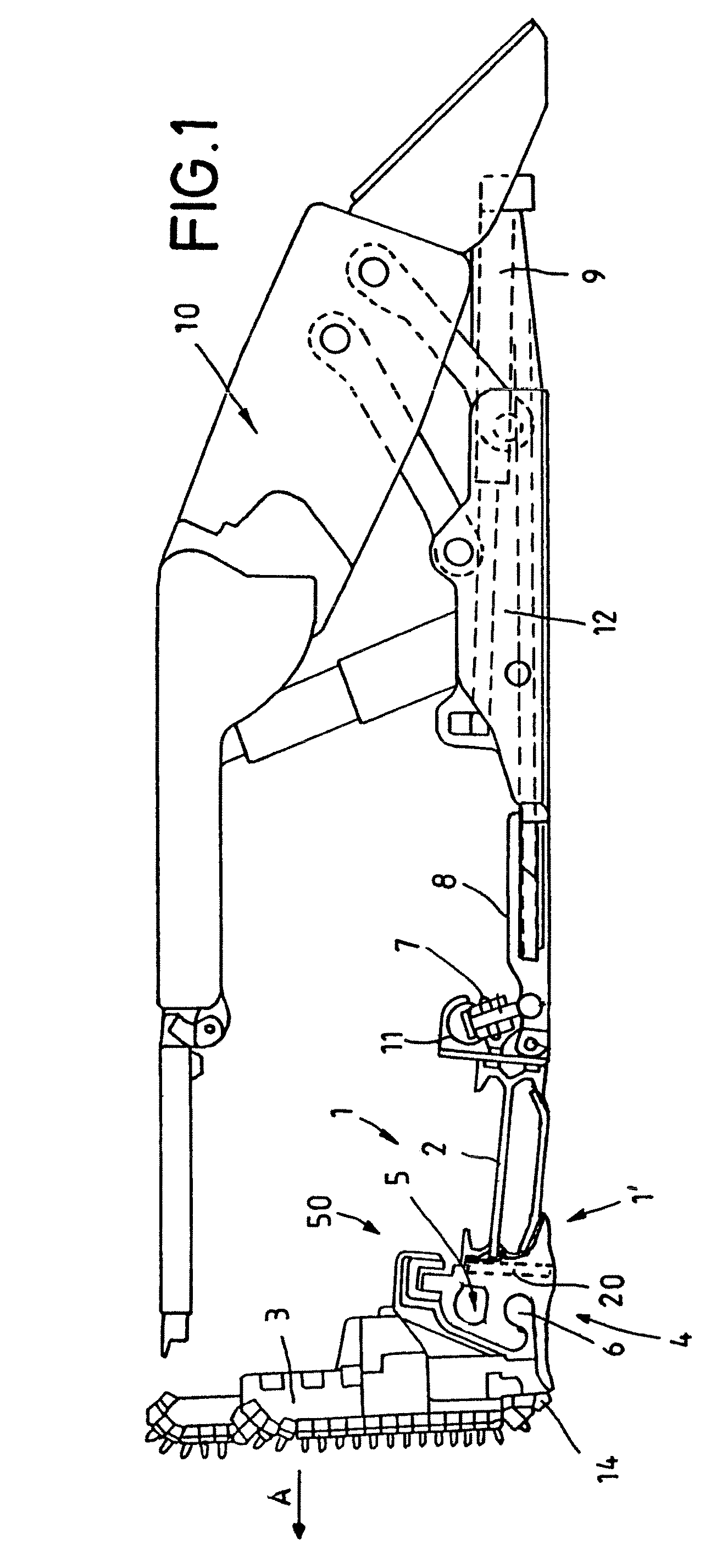
[0021]Referring now to the drawings wherein the showings are for the purpose of illustrating exemplary embodiments of the invention only and not for the purpose of limiting same, the plough system, which is shown diagrammatically in FIG. 1 and the basic design of which is known, comprises a face conveyor 1 which is laid in front of a coal face (not shown) and can be moved in the working direction, in the form of an armored flexible conveyor, of which only one pan element 1′ is shown in FIG. 1. A coal plough 3 which loads the coal which is extracted at the working face in a stripping manner into the face conveyor 1 is guided on the conveyor 1 as winning machine. The correspondingly extracted coal can be conveyed away from the winning operation by way of the face conveyor 1. The coal plough 3 is guided positively on a plough guide or machine guide which is installed as guide section 4 on the working face side in each case on the pan 2 of each pan element 1′ of the face conveyor 1. The...


PUM


Abstract

The invention relates to a device for determining the cutting horizon of a mining winning system, having a movable conveyor which is composed of individual pan elements, and having at least one optical detection sensor which has a sensor head that is received in a sensor carrier and can be pressed with at least one pressure means against a coal / basement rock boundary layer. In order to improve the sensing and working reliability, over the length of the conveyor, a plurality of pan elements are configured as sensor pans which are provided with a protected recess which is open to the basement rock and in which the sensor carrier is arranged or can be arranged such that it can be disassembled together with the sensor head.

Description

[0001]This application claims priority to and the benefit of the filing date of International Application No. PCT / EP2008 / 003086, filed 17 Apr. 2008, which application claims priority to and the benefit of the filing date of German Application No. 20 2007 006 122.6, filed 26 Apr. 2007, both of which are hereby incorporated by reference into the specification of this application.[0002]The invention relates to a device for determining the cutting horizon of a mining winning system, in particular a coal plough system, having a movable conveyor which is composed of individual pan elements which in each case have a conveyor pan having an upper run and a lower run, and a guide section with guide elements which is installed on the working face side as machine guide for an winning machine, and having at least one optical detection sensor for sensing the coal / basement rock boundary layer, which detection sensor has a sensor head which is received in a sensor carrier and can be pressed by at l...

Claims


Application Information

Patent Timeline
Patent Type & Authority Patents(United States)
IPC IPC(8): E21C35/12
CPCE21C27/34E21C35/24E21C35/12
Inventor KLABISCH, ADAMHESSE, NORBERTDUHNKE, KLAUSBETTERMANN, DIEDRICHSIEPENKORT, GERHARD
Owner CATERPILLER GLOBAL MINING EURO GMBH
Why Eureka
Try Eureka