Method for a central venous line catheter having a temperature control system

a technology of temperature control system and catheter, which is applied in the field of catheters, can solve the problems of exacerbate detrimental effects in the brain, prior methods do not provide precise control of patient cooling, and approaches to cooling a patient require excessive time to cool the patient, so as to achieve the effect of increasing the workload of the system

Active Publication Date: 2012-03-06
ZOLL CIRCULATION
View PDF344 Cites 41 Cited by
  • Summary
  • Abstract
  • Description
  • Claims
  • Application Information

AI Technical Summary

Benefits of technology

[0010]By supplementing the known functions of a central venous line catheter with the function of cooling or warming the patient's blood, the present invention takes advantage of existing access to the venous system and a single incision, reducing the risk of additional complications. The access, typically through the subclavian, jugular or femoral veins, is to the central blood supply, via the central venous system, and is therefore particularly expedient, permitting efficient cooling or warming of patient body temperature. The term central venous system generally relates to the portion of the venous system which returns blood to the right heart, including the inferior and superior vena cava. A particular advantage of the invention is that the cooling function is performed efficiently in tandem with a procedure which is known to be likely attended by fever, thus anticipating such fever and facilitating its control. The heat exchange relationship between the system and the central venous system of the patient can be maintained for a prolonged duration—for example, from about one hour to about twenty-nine days.
[0011]The central venous line catheter in accordance with the invention comprises a tubular structure defining a plurality of lumens. At least two of these lumens convey heat exchange fluid to a heat exchange element disposed at a distal, implantable end of the central venous line catheter, while the rest of the lumens serve to provide access to the central blood supply of the patient. The heat exchange element is in fluid communication with a temperature control module via a tubing set which conveys the heat exchange fluid between the components. The temperature control unit, comprising a cooling and / or a heating device, operates in conjunction with a temperature controller to heat or cool the heat exchange fluid depending on a sensed temperature of the patient.
[0012]In a less preferred embodiment, the heat exchanger element of the present invention can be made of metal such as steel, and it can assume an appropriate configuration, such as an accordion-like configuration.
[0013]The system of the invention operates to maintain patient temperature at a desired level. Any deviation from the desired level automatically triggers corrective action, such as circulating the cooled heat exchange fluid through the central venous line catheter to contend with the onset of fever. Additionally, the system is equipped with indicators which signal to the caretaker of the patient the sensed deviation, by for example sensing the increased workload of the system, in order to warn of adverse physiological changes besetting the patient.
[0014]The invention thus provides a system for controlling patient temperature using a central venous line catheter having a heat exchange element. The central venous line catheter is provided with one or more lumens for providing access to the central blood supply of the patient, and with additional lumens for communicating heat exchange fluid to the heat exchange element. Heat exchange fluid temperature is controlled through a feedback loop in which patient temperature is sensed and used to control a temperature control unit comprising a heating device and / or a cooling device in heat exchange relationship with the heat exchange fluid. A tubing set transports the heat exchange fluid between the central venous line and the temperature control unit, with a pump serving to circulate the fluid in a closed fluid circuit in the system.BRIEF DESCRIPTION OF THE SEVERAL VIEWS OF THE DRAWING(S)
[0015]Many advantages of the present invention will be apparent to those skilled in the art with a reading of this specification in conjunction with the attached drawings, wherein like reference numerals are applied to like elements and wherein:

Problems solved by technology

Fever is particularly likely in neuro-ICU patients, and its onset can exacerbate detrimental effects in the brain.
All of these approaches to cooling a patient require excessive time to cool the patient.
Moreover, prior methods do not provide for precise control of patient cooling.

Method used


Image

  • Method for a central venous line catheter having a temperature control system
  • Method for a central venous line catheter having a temperature control system
  • Method for a central venous line catheter having a temperature control system

Examples


Embodiment Construction

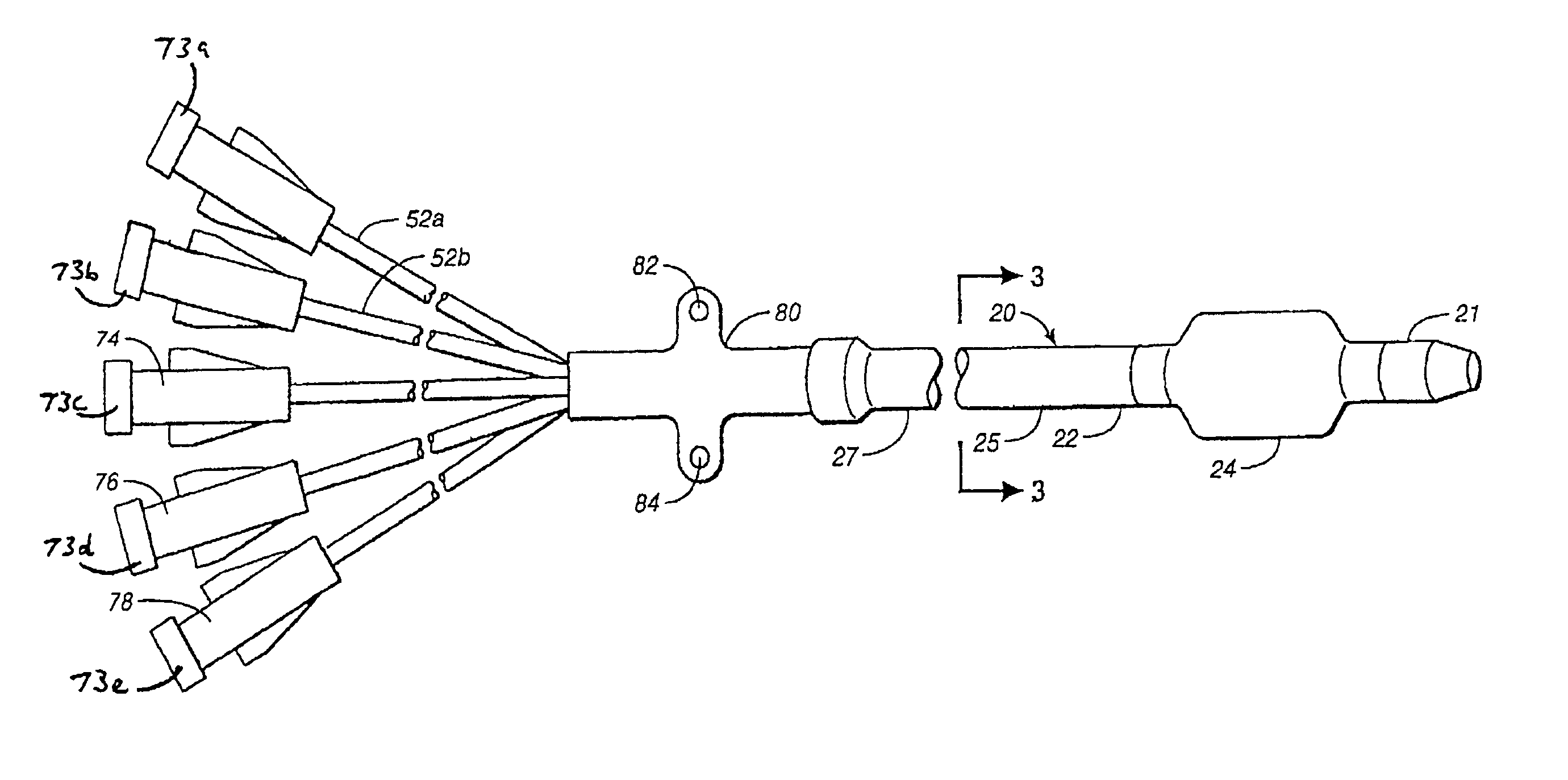
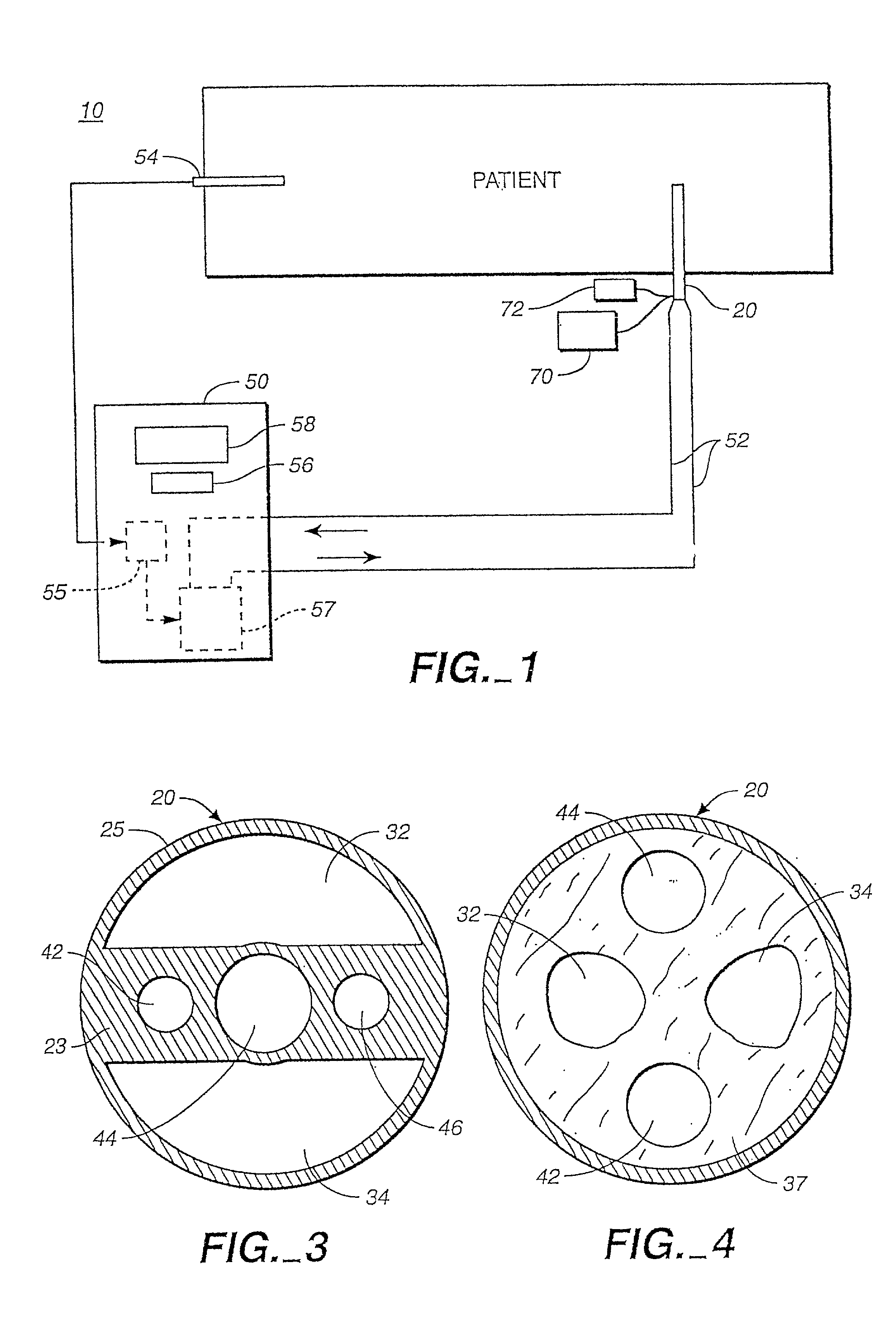
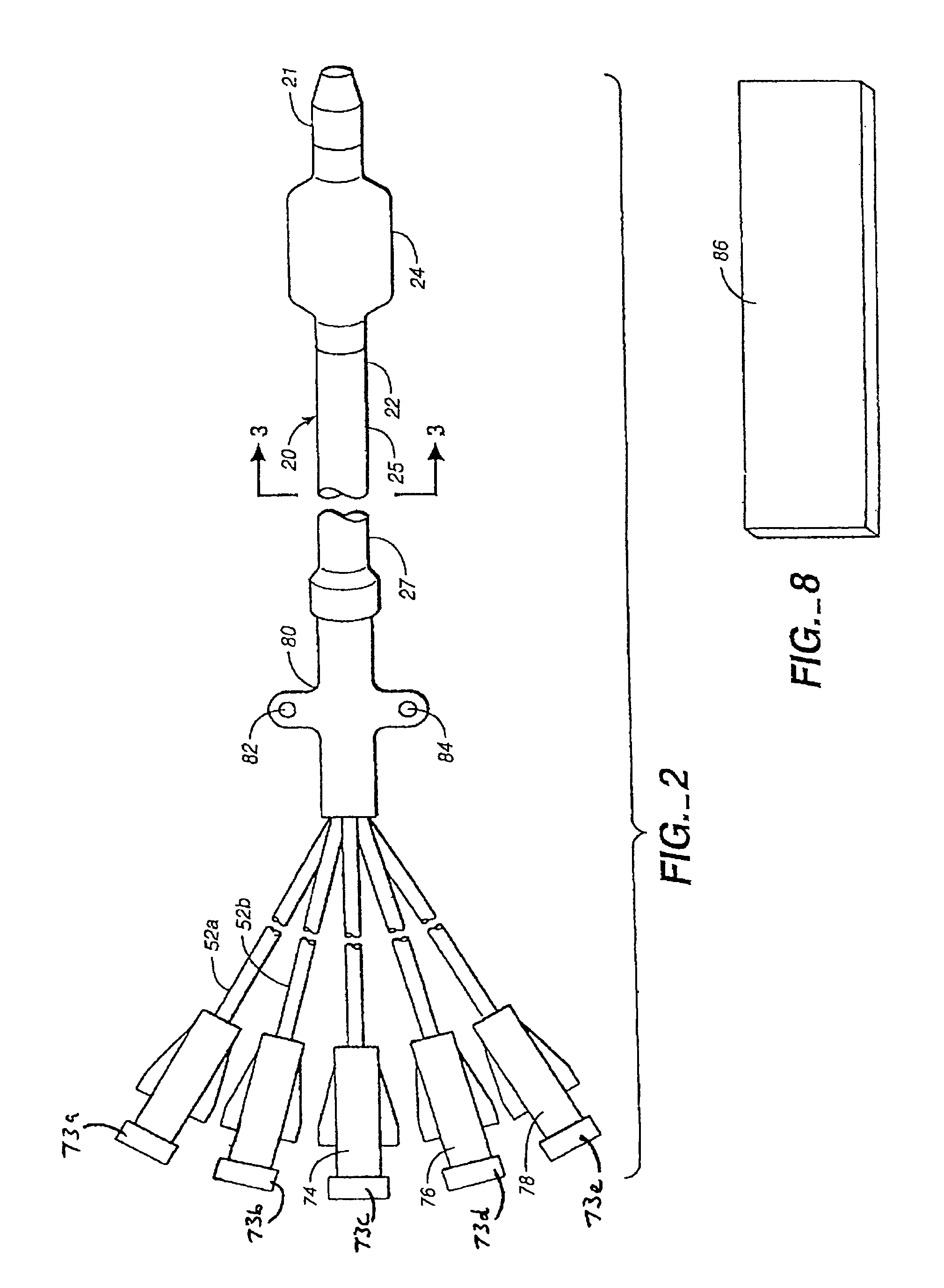
[0025]FIG. 1 shows a temperature control system 10 in accordance with the invention. A central venous line catheter 20 providing access to the central blood supply of the patient is disposed in heat exchange relationship with the patient. Central venous line catheter 20 is provided with a circulating heat exchange fluid (not shown) whose temperature is automatically controlled in accordance with a feedback scheme in order to achieve a desired patient target temperature or temperature range. The feedback schemes involves sensing patient temperature using a probe 54 whose output is provided to a temperature controller 55 housed in a temperature control module 50. The temperature controller 55 determines whether the sensed temperature represents a deviation from the desired temperature or range and selectively activates a heat control unit 57 in order to heat or cool the heat exchange fluid depending on the direction of deviation. As described in more detail below, the central venous l...


PUM


Abstract

A kit of parts comprises a system and instructions for use for controlling patient temperature which uses a central venous line catheter having a heat exchange element. The central venous line catheter is provided with one or more lumens for providing access to the central blood supply of the patient, and with additional lumens for communicating heat exchange fluid to the heat exchange element. Heat exchange fluid temperature is controlled through a feed back loop in which patient temperature is sensed and used to control a temperature control unit comprising a heating device and / or a cooling device in heat exchange relationship with the heat exchange fluid. A tubing set transports the heat exchange fluid between the central venous line and the temperature control unit, with a pump serving to circulate the fluid in a closed fluid circuit in the system.

Description

CROSS-REFERENCE TO RELATED APPLICATIONS[0001]This application is a Continuation of prior U.S. application Ser. No. 09 / 671,114 entitled Kit of Parts Including a Central Venous Line Catheter Having a Temperature Control System, filed on Sep. 28, 2000 now abandoned, which is a Continuation-in-part of U.S. patent application Ser. No. 09 / 253,109 entitled Central Venous Line Catheter Having Temperature Control System, filed Feb. 19, 1999 now abandoned, which is a Continuation-in-part of U.S. patent application Ser. No. 09 / 063,984 entitled Indwelling Heat Exchange Catheter and Method of Using Same, filed Apr. 21, 1998, now issued as U.S. Pat. No. 6,126,684, the disclosures of which are incorporated herein by reference in their entirety.BACKGROUND OF THE INVENTION[0002]1. Field of the Invention[0003]The invention relates to catheters used for access to the central venous blood supply of a patient.[0004]2. Description of Related Art[0005]Catheters such as central venous line catheters are ty...

Claims


Application Information

Patent Timeline
Patent Type & Authority Patents(United States)
IPC IPC(8): A61M29/00A61F7/12A61B17/00A61B18/00A61F2/958A61F7/00A61M1/36A61M5/44A61M25/00
CPCA61M25/02A61F7/123A61M25/002A61F7/12A61B2017/00084A61F2007/0054A61F2007/126A61M1/369A61M5/44A61M25/003A61M25/0032A61M25/10A61M25/1011A61M2025/0036A61M2025/1013A61M2205/36A61M2205/366A61M25/00
Inventor WALKER, BLAIR D.EVANS, SCOTT M.BALDING, DAVID P.BARKER, PETER
Owner ZOLL CIRCULATION
Why Eureka
Try Eureka